
Remote-Controlled Switcher

The described circuit operates effectively as a compact solution for transmitting video and control signals over a single coaxial cable. The system's design incorporates a multiplexer that allows for the selection of one out of eight possible video channels, enabling flexibility in video source management. The use of composite video formats (NTSC, PAL, or SECAM) ensures compatibility with various video equipment.
The interface circuit is critical, as it delivers a stable 10 V supply to the cable while simultaneously handling the channel selection process. The pulsing of the supply voltage serves as a signaling mechanism, allowing the system to communicate channel changes without disrupting the video signal integrity. This is crucial in applications where uninterrupted video playback is necessary.
When the user activates the send button, a digital command is sent as a negative voltage pulse of 1.2 V, which is superimposed on the primary 12-V line. This method of signaling is designed to minimize the impact on the video signal, ensuring that the quality of the transmitted video remains high even during channel switching.
The multiplexer, specifically the Maxim MAX455, is a key component that facilitates the selection process. It is designed to handle analog signals effectively while maintaining low distortion and noise levels. The associated amplifier ensures that the selected video signal is adequately buffered and delivered with the necessary strength to the output.
The digital code generated for channel selection is processed by the integrated circuit components, including Al and IC3A, which decode the signal and communicate with the counter IC2. This counter plays a vital role in determining which video channel is active at any given time, allowing for seamless transitions between different video sources.
Overall, this single-cable system exemplifies efficient electronic design by integrating multiple functionalities into a compact architecture, optimizing the transmission of video and control signals while maintaining signal integrity and operational reliability. This 1-cable system carries composite video (NTSC, PAL, or SECAM), power, and channelselect signals. The interfa ce end of circuit deliver 10 V down the cable, pulses the supply voltage to transmit channel-change connnands, and buffers the received video signal. The multiplexer circuit in Fig. 96-2(a) receives power and control signals over the coaxial cable, while driving the cable with the currently selected video signal.
The interface circuit delivers 10 V to the cable and pulses the supply voltage to select one of 8 channels. When the send button is depressed, a digital burst of 1.2 V amplitude (negative) is superimposed on the 12-V line (as a voltage drop).
This does not affect the video signal. The multiplexer circuit (Fig. 96-2 (c)) consists of a multiplexer and an amplifier. The multiplexer is a Maxim MAX455. The digital code on the supply line is picked off by Al, IC3A, and interfaced to counter IC2, which drives the multiplexer to select the desired video channel.
Related Circuits
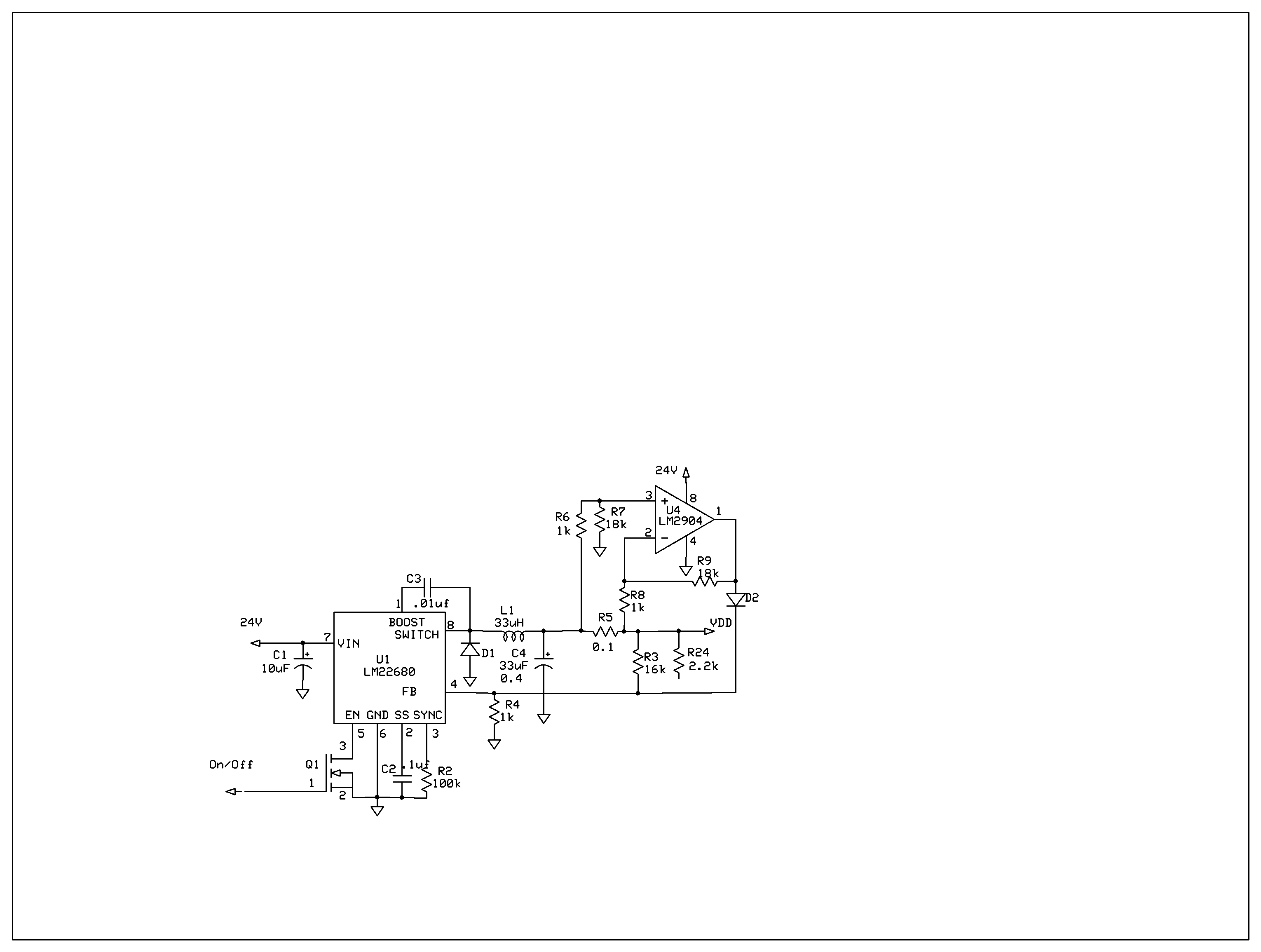
The product requires a voltage-controlled, current-limited power supply. Various switcher chips have been used with an op-amp to provide feedback for a current sense voltage to the feedback pin. Currently, an LM22680 is in use, but it has shown...

This circuit was designed to control power delivery to a Peltier cooler in a vehicle. The power to the load from the vehicle's battery is managed by a Single Pole Double Throw (SPDT) relay. The circuit utilizes an SPDT relay...
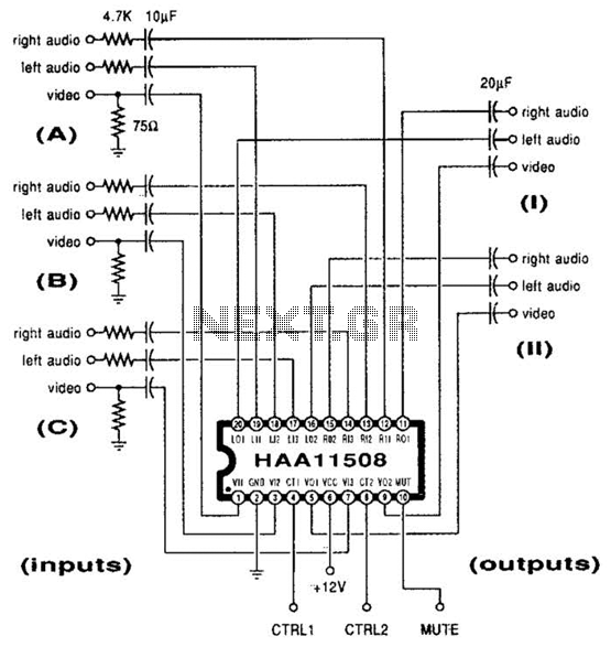
This channel selector selects video and stereo audio from any one of three different sources. The circuit should be constructed on a PC board with plenty of ground plane to minimize noise. The channel selector circuit is designed to facilitate...
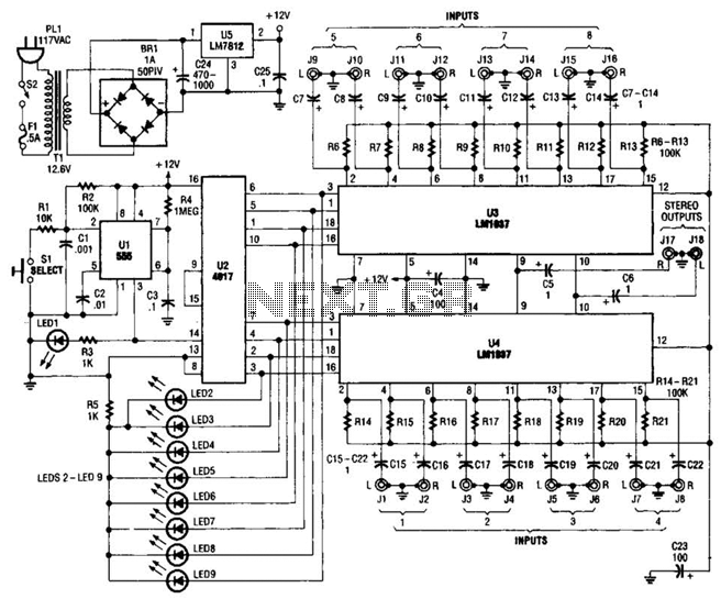
This source is selected by pressing a momentary-contact pushbutton switch (SI). Switch SI is connected to the trigger of a 555 oscillator/timer (U1) configured as a monostable multivibrator, which generates one short output pulse for each press of SI....
This circuit can be used for multiple cameras with one monitor. The circuit can be operated manually or automatically. The described circuit functions as a video switching system, enabling the connection of multiple camera inputs to a single monitor output....
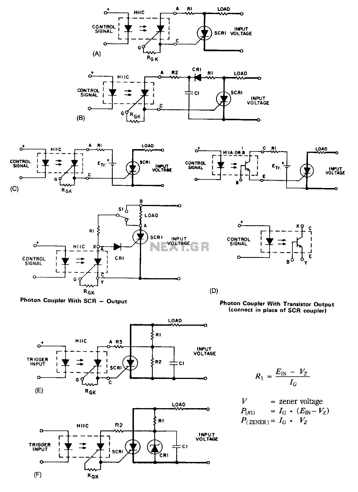
A basic circuit to trigger a silicon-controlled rectifier (SCR) is illustrated in Figure 67-1A. This circuit has the limitation that the blocking voltage of the photonic coupler output device dictates the circuit's blocking voltage, despite the SCR's higher voltage...