
alphanumeric lcd as counter

The LCD module connections are defined as follows: LCD_RS is assigned to PORT RB4, LCD_EN to PORT RB5, LCD_D4 to PORT RB0, LCD_D5 to PORT RB1, LCD_D6 to PORT RB2, and LCD_D7 to PORT RB3. The direction of these connections is also specified. The program initializes the LCD and displays a message indicating "Counter Mode." The main function includes a loop that calls the display initialization function, introduces a 1-second delay, and increments the counter. If the counter exceeds 9999, it resets to 0.
The circuit employs a PIC16F628A microcontroller, which is configured to operate in digital I/O mode by disabling the analog comparator. The LCD is initialized, and the display is cleared before starting the counting process. The display shows the current count value, formatted as a four-digit number.
The connections to the LCD are done in a 4-bit mode, which reduces the number of required data lines, making it suitable for applications with limited I/O pins. The use of a 1-second delay between increments allows for easy observation of the counting process on the LCD display. The software effectively manages the display output by converting the integer count into its ASCII representation for display.
In summary, this circuit demonstrates a simple yet effective application of an LCD in conjunction with a microcontroller to create a counting display. The design emphasizes efficient use of resources and clear output for user interaction.The communication technique with the LCD is the same like the last lesson, and for the current experiment we have added a counter which counts between 0000 and 9999. Our counter increments with 1 second delay. /* ` <7465> * ` Lesson nr. 16: ` Alphanumeric LCD as counter mode. ` Done by: ` Aureliu Raducu Macovei, 2010. ` ` In this exper iment we will work with alphanumeric LCD. Communication ` with LCD will be performed through 4-bits and connections is made as ` follows: D4 with RB0, D5 with RB1, D6 with RB2, D7 with RB3; ` RS with RB4 and EN with RB5. ` To make this project more interesting, a counter is added ` (counts from 0000 to 9999) with a delay of 1 secunde.
` Test configuration: ` MCU: PIC16F628A ` Test. Board: WB-106 Breadboard 2420 dots ` SW: MikroC PRO for PIC 2010 (version v4. 15) ` Configuration Word ` Oscillator: INTOSC:I/O on RA. 6, I/O on RA. 7 ` Watchdog Timer: OFF ` Power up Timer: Disabled ` Master Clear Enable: Enabled ` Browun Out Detect: Enabled ` Low Voltage Program: Disabled ` Data EE Read Protect: Disabled ` Code Protect: OFF ` <7465> * */ // LCD module connections sbit LCD_RS at RB4_bit; // LCD_RS assigned to PORT RB4; sbit LCD_EN at RB5_bit; // LCD_EN assigned to PORT RB5; sbit LCD_D4 at RB0_bit; // LCD_D4 assigned to PORT RB0; sbit LCD_D5 at RB1_bit; // LCD_D5 assigned to PORT RB1; sbit LCD_D6 at RB2_bit; // LCD_D6 assigned to PORT RB2; sbit LCD_D7 at RB3_bit; // LCD_D7 assigned to PORT RB3; sbit LCD_RS_Direction at TRISB4_bit; // LCD_RS assigned to TRIS B4; sbit LCD_EN_Direction at TRISB5_bit; // LCD_EN assigned to TRIS B5; sbit LCD_D4_Direction at TRISB0_bit; // LCD_D4 assigned to TRIS B0; sbit LCD_D5_Direction at TRISB1_bit; // LCD_D5 assigned to TRIS B1; sbit LCD_D6_Direction at TRISB2_bit; // LCD_D6 assigned to TRIS B2; sbit LCD_D7_Direction at TRISB3_bit; // LCD_D7 assigned to TRIS B3; // End LCD module connections char Message1[]="Counter Mode"; // Message for line1; unsigned int number = 0; char *digit = "0000"; void Display_init() // define display_init; { digit[0] = number/1000 + 48; // thousands digit; digit[1] = (number/100)%10 +48; // hundreds digit; digit[2] = (number/10)%10 + 48; // tens digit; digit[3] = number%10 +48; // unit digit; Lcd_Out(2, 7, digit); // display on LCD from column 2, character 7; } void main() // main; { CMCON |= 7; // turn off analogue comparator and make PORTA to digital I/O; Lcd_init(); // LCD Initialization; Lcd_cmd(_LCD_CLEAR); // Clear LCD; Lcd_cmd(_LCD_CURSOR_OFF); // Cursor mode, off; Lcd_out(1, 3, Message1); // display message1 from column 1, character 3; do{ display_init(); // call display_init(); delay_ms(1000); // delay 1s; number +; // Increment number; if (number > 9999u) // if it`s more than 9999 go to 0; number = 0; } while(1); // infinite loop; } // end. 🔗 External reference
Related Circuits
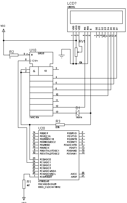
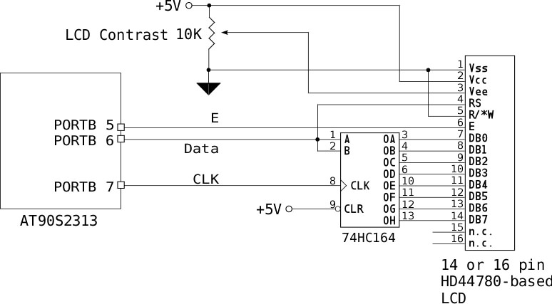
This is not a new idea for interfacing an LCD using two wires, but it can be beneficial in situations where there are insufficient microcontroller pins. This example is based on the Hitachi 44780 alphanumeric LCD. The provided circuit...
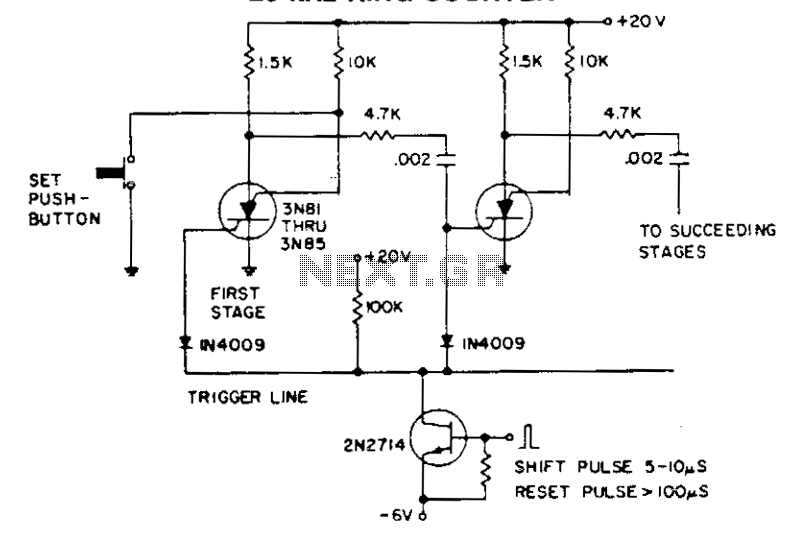
The shift pulse deactivates the conducting silicon-controlled switches (SCS) by reverse biasing the cathode gate. The charge accumulated in the coupling capacitor subsequently triggers the following stage. An excessively prolonged shift pulse charges all capacitors, resulting in the deactivation...
The PSoC 3 Primer Kit is specifically designed to assist students in mastering the necessary skills in embedded systems. The kit is structured to enable easy utilization of all possible features of the microcontroller. It supports the FX2LP Programmer,...
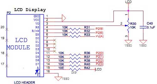
If no characters are displayed on the LCD and the hardware and software have been verified as functional, adjust the LCD Contrast potentiometer until the characters become visible. To send an 8-bit character or command to the LCD via...
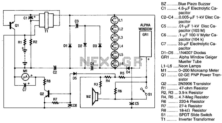
Q1 is a PNP power transistor used in conjunction with a ferrite transformer to form a blocking-type oscillator. This oscillator operates at a fixed frequency, with feedback for sustaining oscillations provided by capacitor C1. Due to the turns ratio...
Frequency measurement is crucial in radio construction, as it allows for the setting of desired frequencies in both receivers and transmitters, as well as monitoring frequency drifts. A frequency counter can verify oscillator functionality and ensure stability in generation....