
Geiger Counter Ii Circuit

The circuit described utilizes a PNP power transistor (Q1) and a ferrite transformer (T1) to create a blocking oscillator, which is a common configuration for generating high-frequency signals. The feedback mechanism, facilitated by capacitor C1, ensures that the oscillator maintains a stable frequency. The transformer steps up the voltage from the primary to the secondary winding, significantly increasing the output voltage, which is essential for applications requiring high voltage levels.
The voltage tripper stage serves a critical function in regulating the high voltage output. Capacitors C2, C3, and C4 work in conjunction with diodes D1, D2, and D3 to manage and stabilize the voltage, ensuring that it remains within safe operational limits, despite fluctuations in input. The use of neon lamps L1 to L6 adds an additional layer of voltage regulation, providing visual feedback when the voltage reaches a specific threshold.
Diode D4 plays a crucial role in converting the high-voltage AC signal into a DC signal, which is then supplied to the GM tube's cathode. The GM tube is a gas-filled detector that responds to ionizing radiation. When a radioactive particle interacts with the gas, it ionizes the gas, creating a pulse that signifies detection. This pulse is then used to drive a piezo speaker, providing an audible indication of radiation detection.
Transistor Q2 serves as an integrator for the pulses generated by the GM tube, utilizing capacitor C6 to smooth the output and convert the pulse train into a proportional DC voltage. This voltage is indicative of the radiation level detected, allowing for easy monitoring through the attached meter. The configuration ensures that the collector of Q2 connects to the meter via resistor R8, providing a clear and direct measurement of radiation levels, while the meter is powered by a battery, ensuring portability and ease of use in various environments. Ql is a pnp power transistor used in conjunction with a ferrite transformer to form a blocking-type oscillator. This oscillator is a fixed- frequency type, and the feedback to sustain oscillations is from capacitor CI.
Because of the turns ratio of Tl, the small ac voltage produced oil its primary is converted to a large ac voltage on its secondary. That high-voltage ac is applied to the voltage tripper stage, which consists of capacitors C2, C3, and C4 and diodes D1, D2, and D3.
The resultant voltage is now over 800 V and.it is regulated by neon lamps LI through L6. Diode D4 rectifies the high voltage and applies it to the cathode lead of the GM tube. The positive (+) bias on the GM tube is applied to the anode by way ol`load resistors R4 and R5. Each time a radioactive particle strikes the GM tube, it causes the gas inside to ionize. This ionization of the gas creates a pulse, which drives the piezo speaker and is also coupled by diode D5 to the base of Q2, Transistor Q2 is a pnp type and is used to integrate the pulses in conjunction with capacitor C6. That produces a dc voltage level, which is in proportion to the quantity of pulses arriving at the base of Q2.
The collector of Q2 is connected through resistor R8 to the (+) terminal of the meter. The other side of the meter goes directly to (-) of the battery.
Related Circuits
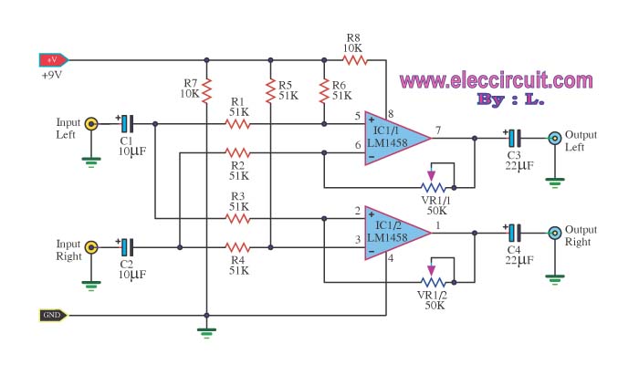
The LM1458 integrated circuit (IC) is utilized to amplify the difference in the left input signal (L), resulting in a surround sound effect. The left signal is coupled through capacitor C2 and resistor R1 to pin 5 of IC1...
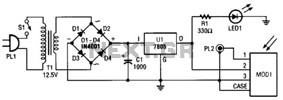
A schematic diagram for the remote analyzer is presented. The circuit is powered by a simple 5-V supply, which includes components such as PL1, SI, Tl, a bridge rectifier formed by diodes D1 through D4, capacitor CI, and a...

This simple circuit indicates the status of a phone, including Line OK, Dialing, and Call Attended. It also features a locking mechanism to block outgoing calls while allowing incoming calls, preventing misuse of the telephone. The circuit requires only...
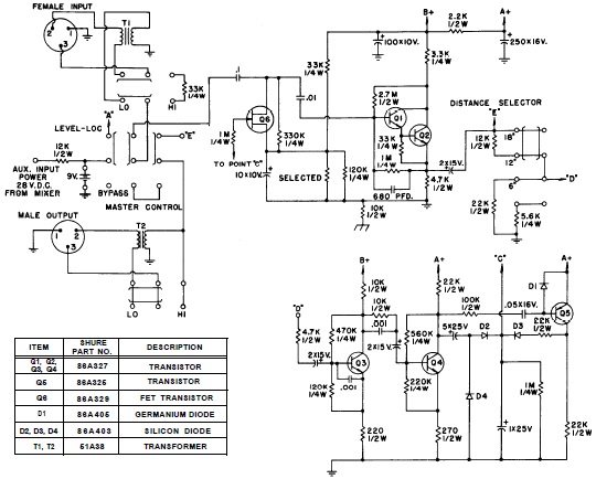
SHURE is an American corporation that manufactures consumer and professional audio electronics, including microphones, phonograph cartridges, and discussion systems. SHURE Incorporated is a well-established entity in the audio electronics industry, recognized for its innovative design and high-quality products. The company...
The 555 timer is utilized as a clock source to drive the RS7490 decimal counter, providing a BCD output to a 7-segment LED display. The clock frequency can be adjusted by changing the value of resistor R1. The circuit operates...

The TDA6106Q test circuit, as depicted in the provided figure, operates with a feedback factor of 1/116. The input signal, Vin, is received from the input network consisting of resistors R1, R9 and capacitors C1, C2. The TDA6106Q IC...