
Altec 1566 vacuum tube mic preamp and direct box

The circuit utilizes 12AX7 dual triodes, where V1 acts as a Class A voltage amplifier while V2 functions as a Cathode Follower. The Common Cathode configuration of V1 allows for effective voltage amplification, leveraging the high input impedance characteristic of vacuum tubes. V2's Cathode Follower design provides current gain, maintaining a low output impedance, which is crucial for driving loads effectively.
The input transformer plays a vital role in impedance matching, converting low impedance signals from microphones to high impedance suitable for the tube circuitry. This conversion is essential for minimizing signal loss over long cable runs, ensuring that the integrity of the audio signal is maintained. The output transformer then matches the output impedance to a level that can effectively drive speakers or other audio equipment while reducing susceptibility to noise and interference.
The filament circuit requires careful consideration, as it powers the cathodes of the tubes. The choice between parallel and series wiring affects the voltage and current requirements. The design must accommodate the filament's power needs, ensuring stable operation without introducing hum or noise into the audio signal. With a current requirement of 150 mA per filament, the total draw for two tubes in parallel is 300 mA, which must be supplied by the power supply.
The output characteristics of the amplifier are designed to handle specific signal levels, with the circuit optimized for operation at -10 dBm and capable of handling peaks up to +15 dBm before clipping occurs. This design allows for a wide dynamic range, making the circuit suitable for various audio applications, including public address systems and recording equipment.
Overall, the design of this circuit exemplifies the principles of tube amplification, focusing on impedance matching, signal integrity, and efficient power management to achieve high-quality audio performance.V1 and V2 are 12AX7 dual triodes. Each half of V1 is wired as a Class A voltage amplifier in a configuration known as Common Cathode. By comparison, both halves of V2 are wired together in the Cathode Follower configuration for current gain. Don ’t freak dudes and dudettes! Tubes are real high impedance (Hi-Z) devices — just like a passive guitar or bass — and, in addition to making things louder (voltage gain), they can also convert impedance — in this case — from high to medium (current gain). Unlike transformers, tubes and transistors can manipulate impedance without a level loss. Remember, the outside world is a nasty place. Have you ever had an instrument cable that crackled when stepped on That phenomenon is not an example of a bad cable so much as it ’s the wrong cable for the application.
(It ’s capacitance is too high and the insulation between conductors is inadequate. ) The reason there are transformers at both the input and the output is to match impedance with the outside world. Low-impedance (Lo-Z) balanced sources, such as microphones outfitted with XLR connectors, can drive long lengths of cable.
The input transformer converts Lo-Z to Hi-Z and in doing so takes a small signal and steps it up to a higher albeit more vulnerable signal. (The power supply transformer manipulates voltage and current in the same way. ) After the tubes do their thang, the output transformer brings the impedance down to a level that ’s semi-impervious to electrical interference.
While on the subject, the filament in a vacuum tube heats the cathode so that it will emit electrons, which are negatively charged. The high voltage at the plate accelerates and attracts the electrons while the grid controls electron flow.
Each 12AX7 filament requires 150 milliamps (mA) so that the two in parallel draw 300mA total. By comparison, the plate current can be calculated by taking the voltage drop across any plate resistor. For example, R4 has 135vdc on one side and 105vdc on the other. The voltage drop across R4 is 30 volts, therefore, using Ohm ’s Law, (I=V/R) the current is. 3 mA with no signal applied. The filament current is 500 times that of the plate! The 1566A included 8-pin (octal) tube-style sockets into which plug-in transformers or dummy plugs were inserted for balanced or unbalanced operation, respectively.
Input and output connections were via barrier strips. The intended application was as a mic amplifier for a public address system. ("Attention K-mart Shoppers!") When operated at a nominal -10 dBm (yes, please terminate into 600 ohms), the 1566A is acceptably clean. If you crank it so that the nominal level is +4 dBm, peaks will be sweetly saturating at +15dBm and asymmetrical clipping starts at about +17 dBm.
It ’s the perfect "Electric Crayon. " Yes, you`ll need Phantom Power! The good news is that I finally got `round to writing an article for the July`97 issue of EQ Magazine. Even better (for surfing geeks), is that the heading above is the link to high-voltage love! This transformer could be configured to provide all of the necessary voltages - including phantom - although the filament voltage will require regulation.
No shielding, and it is a big tranny! When building a power supply for a vacuum tube circuit, there are many things to consider. For the Altec 1566, there is no simple answer - just many options - each with it ’s own pluses and minuses. Vacuum tubes require two voltage sources, one for the filament (like a light bulb) and one for the plate).
The filament for the 12A 7 family can be wired in parallel (6. 3v @ 300 milli-amps or mA) or in series (12. 6v @ 150mA). There are two triode amplifiers within each 12A 7. The plate circuit for each amplifier requires about 1mA. When you look at the power transformers above, you ’ll see that ALL have way more current capacity than required, because most are commonly available replacements for Fender guitar amps. The 🔗 External reference
Related Circuits
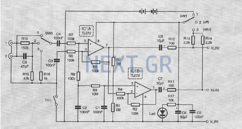
The sound is captured from a musical instrument in two different ways: through a microphone connected to the instrument's amplifier or via a direct connection to the mixing console using a direct-box device. The advantage of using a direct-box...
This document describes a simple 2.4 GHz SWR meter that utilizes surplus microwave hardware. The main component is a MECA -20/-20 dB Directional Coupler, which operates within a frequency range of approximately 700 MHz to 2.5 GHz. This directional...
The diode tube under examination is essentially Edison’s early incandescent bulb containing a plate. The term "diode" refers to the two elements or electrodes within the glass container that constitute the tube. Shortly after the discovery of the Edison...
Many applications require a large number of keys connected to a computing system. Examples include PC keyboards, cell phone keypads, and calculators. Connecting a single key to a microcontroller unit (MCU) is straightforward; however, connecting 10 or 100 keys...
More: A comprehensive electronic schematic is required to illustrate the functionality and interconnections of various components within a circuit. The schematic should clearly depict the arrangement of components such as resistors, capacitors, diodes, transistors, and integrated circuits, along with...
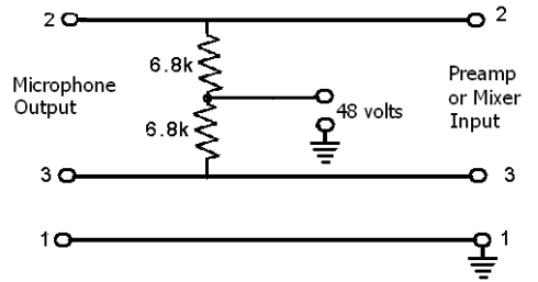
These devices require power to operate. This power can be supplied by a battery inserted into the microphone, a separate dedicated power supply with a specialized multi-pin cable, or most commonly, phantom power. Phantom power is supplied by a...