
New latest Simple SWR Meter 2.4 GHz 20 dB Directional Coupler

The hardware components include the large blue directional coupler and an N-connector female-to-female adapter required to connect to the Narda 5 Watt, 50-ohm load. The diode detectors, which are the silver components on top, are identical and contain 1N23 point-contact diodes. Their voltage output is provided through integrated BNC connectors. These diode detectors are sometimes referred to as "crystal" detectors. The 1N23 diodes may be challenging to source, but Fair Radio stocks them, and they can also be found as mixer diodes in some 10 GHz gunnplexer-based automatic door openers.
The schematic for the 2.4 GHz SWR meter incorporates a MECA -20/-20 dB Directional Coupler, which is essential for measuring the reflected and forward power in the antenna system. The two output ports of the coupler are connected to diode detectors, which rectify the RF signals into DC voltages. These detectors are critical for providing a voltage proportional to the power levels at each port. The 1N23 diodes, known for their fast response times and effectiveness in microwave applications, serve as the heart of these detectors.
The oscilloscope is utilized to compare the DC voltages from the two diode detectors, allowing for real-time monitoring of the SWR. The setup ensures that measurements reflect the actual performance of the antenna system. The use of an N-connector female-to-female adapter facilitates a secure connection to the 50-ohm load, ensuring minimal signal loss and accurate readings.
When assembling the SWR meter, attention should be paid to the layout and connections to minimize any potential interference or signal degradation. Proper calibration of the oscilloscope and ensuring that the measurement points are correctly identified will enhance the accuracy of the SWR readings. This SWR meter is particularly valuable for amateur radio operators and professionals who require reliable measurements of their antenna systems in the 2.4 GHz frequency range.Here is a simple 2. 4 GHz SWR meter which can be easily found, which is based around surplus microwave hardware. The main component is a MECA -20/-20 dB Directional Coupler which has a frequency range of approximately 700 MHz to 2. 5 GHz. This particular directional coupler above has two ports, each coupled by 20 dB. What that means is, a signal is "coupled" to these ports which is identical to the main signal passing through the directional coupler, only it`s attenuated by 20 dB. By placing diode detectors on the outputs of these two ports and comparing the resulting voltages on an oscilloscope, you can quickly determine the integrity of your antenna system in reference to 50 ohms.
Be sure to measure SWR at the antenna! Feedline loss will attenuate the signal and give you a false SWR reading if you measure it directly at the transmitter`s RF output. Don`t be like those guys at Field Day who brag about their radio`s (internal) SWR reading when connected to a homebrew antenna with 200 feet of Radio Shack RG-58 and banana clips.
Also, don`t trust "analog" movement reading SWR meters when dealing with digital data transmitters. The needle response time isn`t fast enough to provide an accurate reading. Overview of the hardware components used. The directional coupler is the large blue thing. A N-connector female-to-female adapter is needed to connect the Narda 5 Watt, 50 ohm load. The diode detectors are the silver things on top. They both are identical and house 1N23 point-contact diodes. Their voltage output is via integrated BNC connectors. Close up view of the diode detectors. They are sometimes referred to as "crystal" detectors. 1N23-style diodes can be hard to find. Fair Radio does carry them. You can also find them used as mixer diodes in some 10 GHz gunnplexer-based automatic door openers. 🔗 External reference
Related Circuits
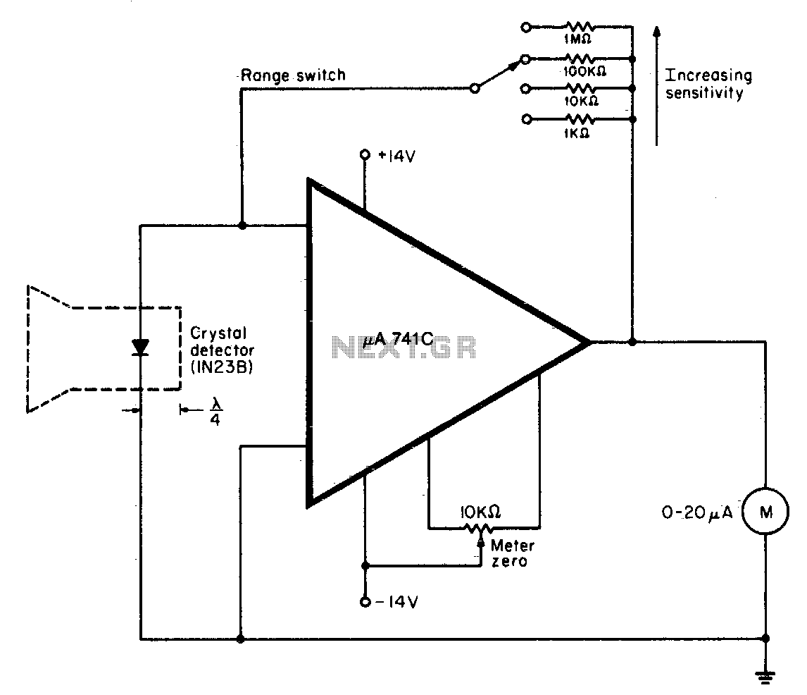
A waveguide directs energy onto a crystal detector during operation. The diode utilized is designed for X-band operation. The waveguide consists of a 1-inch piece of plastic tubing with flared ends. The plastic surface is treated with an electroless...
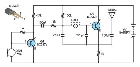
This AM transmitter is designed for simplicity and ease of construction. It utilizes a single-winding inductor that is not tapped, eliminating the need for custom winding. A readily available RF choke, such as the Jaycar Cat LF-1536, can be...
The design of the digital logic probe centers around a pair of complementary bipolar transistors, which, in this application, are used as electronic switches. The digital logic probe is a diagnostic tool utilized for testing and analyzing digital circuits. The...
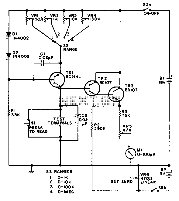
This circuit is designed to provide accurate measurement and a linear resistance scale at the high end. The circuit has four ranges. Additionally, another meter with a current range of 10 µA to 10 mA and a sensitivity of...
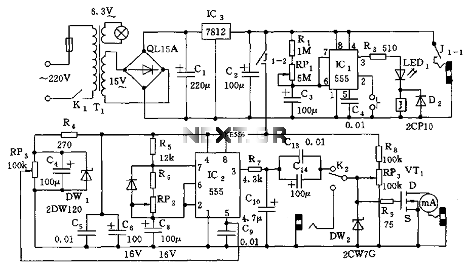
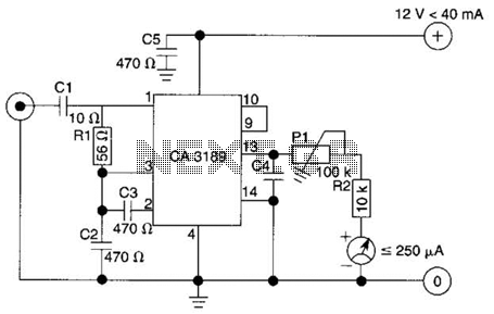
The information apparatus includes a buck rectifier power supply providing Vdd at +12V, a timing circuit, a multivibrator, and the output from the first amplifier. The components R1, RP1, and C3 are used to initiate timing, with the timing...
In certain situations, it is beneficial to enhance the range of available control, and this circuit serves that purpose by receiving the infrared (IR) signal from a remote control and re-transmitting it, potentially around corners or into other rooms....