
AM loop antenna project


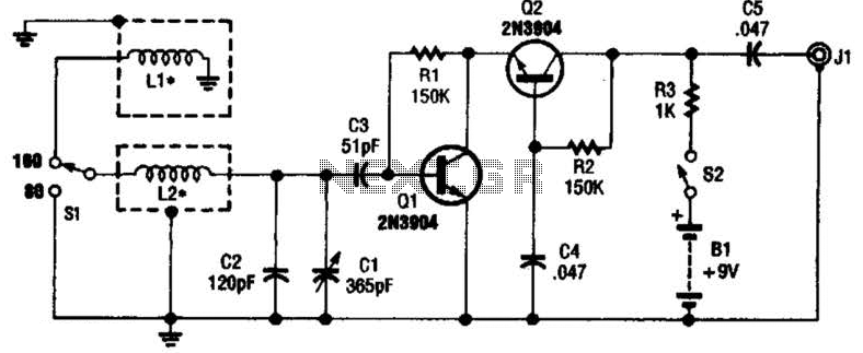
The loop antenna described is an efficient device for enhancing medium wave radio reception, particularly within the frequency range of 550 to 1700 KHz. Its design consists of a loop formed from #35 copper wire, wound in 16 turns, which contributes to its resonant characteristics and overall performance. The physical dimensions of the loop, measuring 15 inches on each side and 1.5 inches in width, are optimal for achieving a balance between size and performance, as larger loops generally yield better reception.
The antenna's directional nature allows it to effectively capture signals aligned with the plane of the windings while minimizing interference from signals that are perpendicular. This characteristic is particularly advantageous for improving the signal-to-noise ratio, thus enhancing the clarity of the desired broadcast. The Q factor of approximately 100 at 600 KHz indicates a reasonably good selectivity, allowing the antenna to filter out unwanted frequencies while maintaining a bandwidth of about 6 KHz.
Tuning is achieved through a variable capacitor rated between 30-365 pF, which allows the antenna to be adjusted to resonate at different frequencies within the medium wave band. This tuning capability is essential for optimizing reception as it accommodates the varying frequencies of broadcast signals.
Inductive coupling to the radio's internal ferrite rod antenna eliminates the need for physical connections, simplifying the setup process. Users can achieve optimal reception by positioning the radio in proximity to the loop antenna and making adjustments to both the radio and antenna tuning as necessary. This flexibility ensures that the user can fine-tune the system to achieve the best possible reception for their specific environment and signal conditions.A loop antenna can greatly improve medium wave reception. Loop antennas are directional and receive signals along the plane of the windings. The directional quality improves signal to noise ratio of the desired signal while rejecting signals perpendular to the plane of the windings. Larger loops are better than smaller ones but good results can be obtained from moderate sizes of one or two feet on a side.
The shape doesn't make much difference so the loop can be circular, rectangular or a triangle shape. The main idea is to cover as much area as possible, so I would imagine a circular loop would be the best. The loop pictured here measures 15 inches on a side and is about 1.5 inches wide. It was wound with 16 turns of #35 copper wire, and has a Q of about 100 at 600 KHz. Larger guage wire might have been better (less resistance) and therefore higher Q and selectivity, but the arrangment here works pretty well with a bandwidth of about 6Khz at 600Khz.
The loop is tuned with a 30-365 pF capacitor and covers the standard broadcast band of 550-1700 KHz. The antenna signal is inductively coupled to the radio's internal ferrite rod antenna so no wire connections are needed.
Simply place the radio near the loop antenna and adjust the position(s) for best results. You may have to adjust the tuning of both the radio and antenna several times for optimum results. 🔗 External reference
Related Circuits
This project is designed for a quiz competition involving up to four contestants or teams. Each contestant is equipped with a trigger push-switch and an LED. When a trigger switch is activated, it illuminates the corresponding LED, activates a...
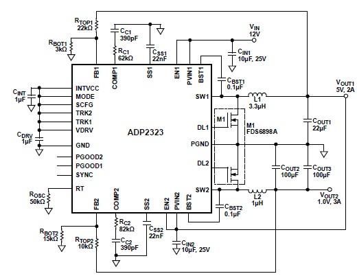
The ADP2323 DC-DC converter is designed to deliver two output voltages with specified maximum output currents. The first channel provides a 5-volt output with a maximum current of 2 Amperes, while the second channel supplies 1 volt with a...
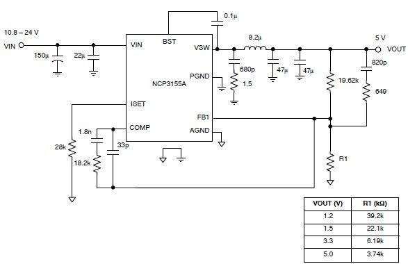
This 5-volt regulated power supply circuit project is designed using the NCP3155 DC-DC switching regulator, which features fully integrated power switches and comprehensive fault protection. The circuit requires only a few external electronic components and delivers a fixed output...
This antenna may assist in minimizing power-line noise. It consists of a plastic hula hoop or conduit with a diameter of 3 feet, which is covered with aluminum foil to serve as a shield for LI and L2. LI...
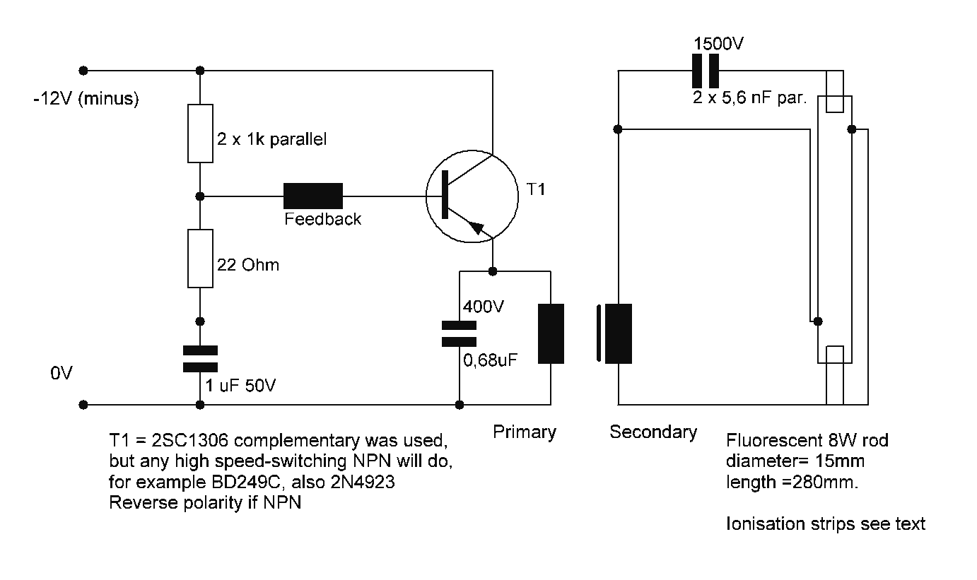
Starting a fluorescent lamp on an inverter can be challenging due to the trade-offs involved in achieving optimal operating efficiency with 12V drivers. Fluorescent lamps require a specific starting voltage to ionize the gas within the tube and initiate the...
This UHF antenna amplifier circuit, also referred to as a UHF antenna booster circuit, is designed to amplify signals within the UHF band, specifically from 400 MHz to 850 MHz. The circuit employs a single transistor and provides an...