
Fluorescent Lamp Driver Circuit and Project

Fluorescent lamps require a specific starting voltage to ionize the gas within the tube and initiate the lighting process. In inverter applications, particularly those utilizing 12V systems, the challenge lies in providing sufficient starting voltage while maintaining energy efficiency.
An inverter circuit designed for fluorescent lamps typically includes several essential components: a DC-DC converter, a high-frequency oscillator, and a transformer. The DC-DC converter steps up the 12V input to a higher voltage necessary for starting the lamp, often reaching levels around 400V to 600V. The high-frequency oscillator generates a pulse-width modulated (PWM) signal that drives the transformer, allowing for efficient energy transfer and higher output voltage.
The transformer used in this application is crucial; it must be designed to handle the high-frequency operation and provide isolation between the high-voltage output and the low-voltage input. Additionally, the design may include feedback mechanisms to regulate the output voltage and current, ensuring stable operation as the lamp warms up and reaches its steady state.
To enhance efficiency, the inverter may incorporate features such as soft-start circuits, which gradually increase the voltage applied to the lamp, reducing stress on the lamp and extending its lifespan. Furthermore, the circuit may include protective components like fuses or circuit breakers to prevent damage from overcurrent conditions during startup.
In summary, designing a 12V driver for fluorescent lamps on an inverter involves careful consideration of voltage requirements, component selection, and efficiency optimization to ensure reliable operation and longevity of the lamp.Starting a fluorescent on an inverter The 12V drivers for fluorescent lamps are tricky, because of the compromise between a good operating efficiency 🔗 External reference
Related Circuits
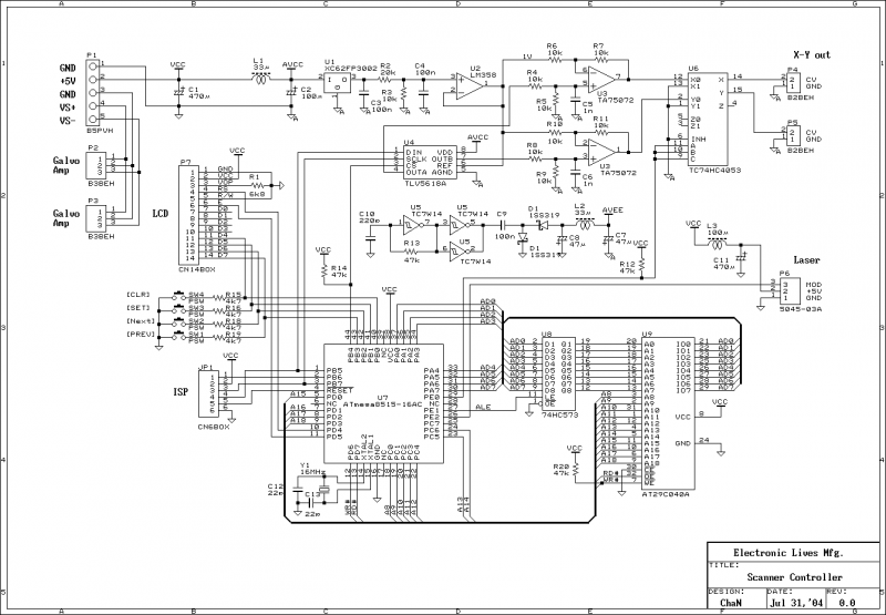
This document outlines the servo amplifier and its circuit diagram. It describes a straightforward operational amplifier circuit that integrates both a power amplifier and a small signal amplifier on the same board. Care must be taken to avoid unintended...
A device designed to locate a mobile phone by emitting intermittent flashes and beeps, indicating the presence of an active mobile phone. This circuit activates even when the mobile phone is in silent mode, making it effective for detecting...

A voltage comparator is a device that compares the voltages at its two inputs and generates an output based on the comparison. It produces a high output when the positive input exceeds the negative input and a low output...
This schematic is provided with the intention of being useful, but it comes without any warranty, including implied warranties of merchantability or fitness for a particular purpose. The address bus in this schematic is connected in a unique manner,...
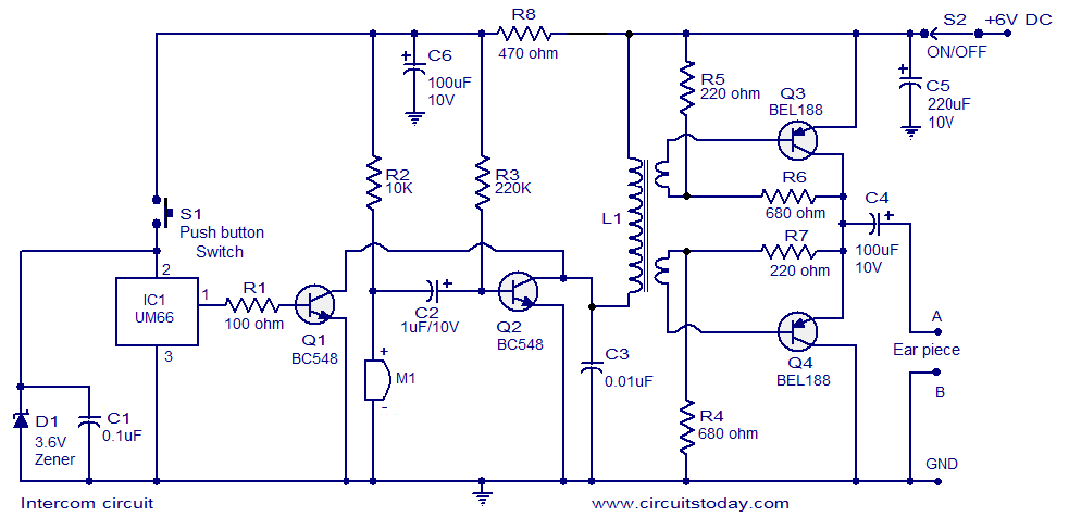
A straightforward intercom circuit designed using transistors. It does not require a changeover switch and can be used similarly to a telephone. This intercom circuit utilizes transistors to facilitate communication between two or more stations without the need for complex...
The development of the entire system necessitated a thorough identification of all processes related to the laser controller. The initial diagram outlines the primary physical components utilized in the CNC laser system. The setup includes a power supply, a...