
AM radio circuit based on TDA1572. 9V operation2W output
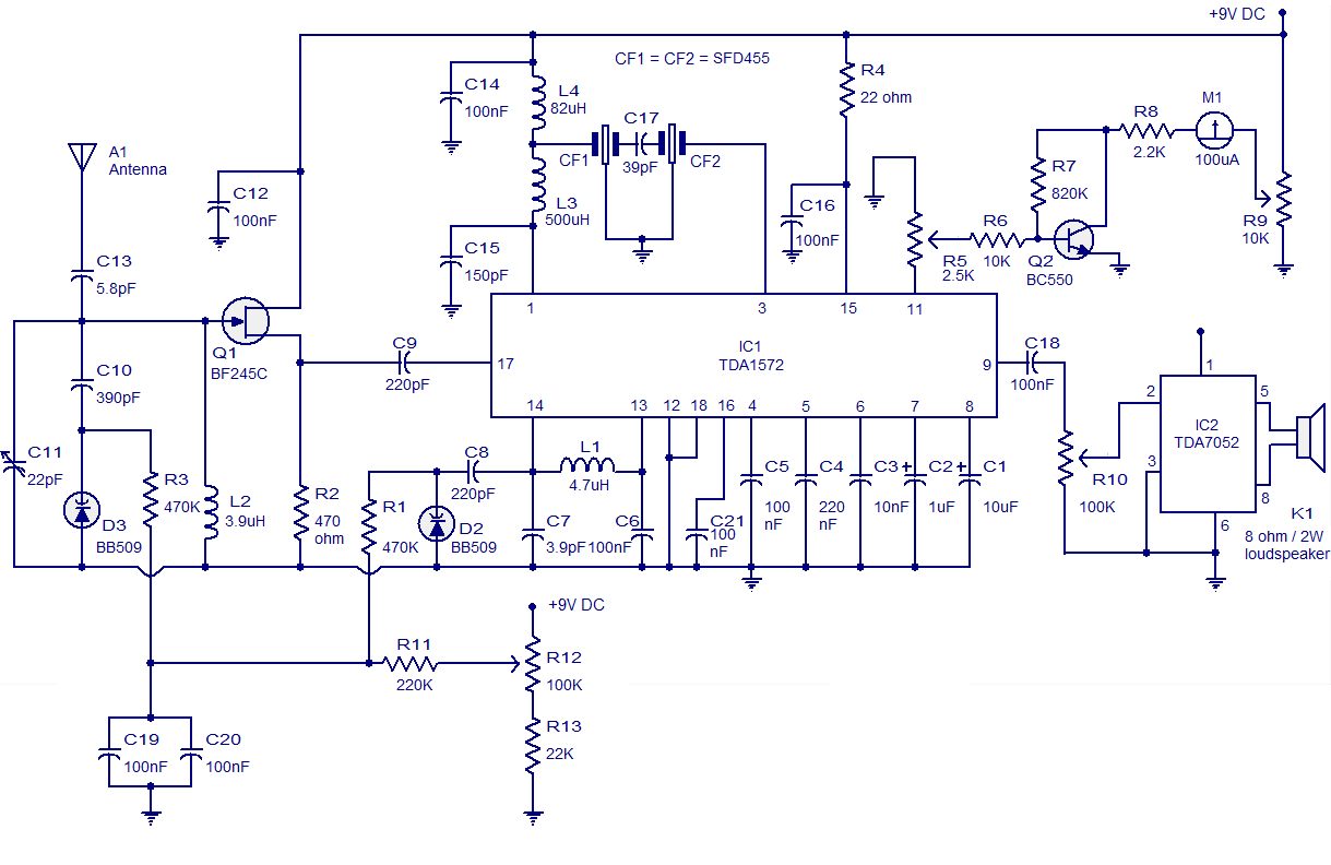
The AM radio circuit utilizing the TDA1572 integrated circuit (IC) is designed for efficient reception of amplitude modulated signals. This circuit is particularly notable for its simplicity and high performance, making it suitable for various applications in audio broadcasting.
The TDA1572 IC is a versatile device that integrates several functions essential for AM radio operation. It features a built-in RF amplifier, demodulator, and audio amplifier, which collectively streamline the design by minimizing the need for additional discrete components. The circuit is powered by a 9V DC supply, which is common for portable and battery-operated devices, ensuring ease of integration into various systems.
The output power of 1W is adequate for driving small speakers or headphones, providing clear audio output for personal listening. The design typically includes a simple tuning circuit, which may consist of a variable capacitor and inductor to allow the user to select different AM frequencies. This tuning mechanism is crucial for optimizing the reception of desired radio stations.
Additionally, the circuit may incorporate basic filtering components to enhance the audio quality and reduce noise. Capacitors and inductors are often used to create low-pass or band-pass filters that can improve the clarity of the received signal. The overall layout of the circuit should be carefully considered to minimize interference and maximize performance.
In summary, the AM radio circuit based on the TDA1572 IC is a well-engineered solution that balances performance and simplicity, making it an excellent choice for both hobbyists and professionals looking to implement AM radio functionality in their projects.High quality AM radio circuit based on TDA1572 IC. The AM radio receiver circuit operates from 9V DC and has 1W output power. Requires minimum external components.. 🔗 External reference
Related Circuits
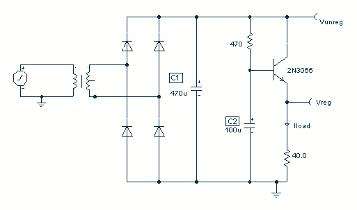
To avoid excess ripple output on a power supply feeding a heavy load, usually a large value capacitor is chosen following the rectifier. In this circuit, C1 is only a 470uF capacitor. The gyrator principle uses the effect that...

The schematic for this project flows naturally from left to right, starting with the antenna and the regenerative receiver front-end, followed by amplification stages, and concluding with the 555 timer. This regenerative receiver front-end is commonly found in circuits...
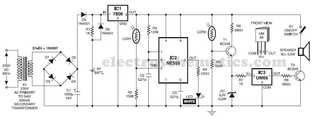
This musical light alarm circuit is very simple and uses only seven components, including a light-dependent resistor (LDR) and a 3.6V battery or three 1.2V rechargeable batteries. The well-known UM66 is utilized as the sound generator, providing a pleasant...
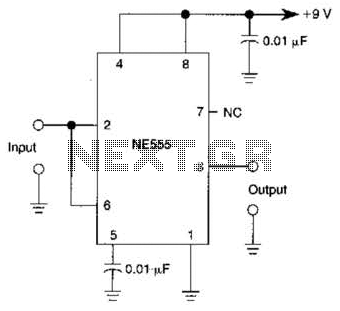
A 555 IC is configured to function as a Schmitt trigger. Inputs above and below the threshold level will turn the circuit on and off, producing a square wave output. The 555 timer integrated circuit (IC) is a versatile device...
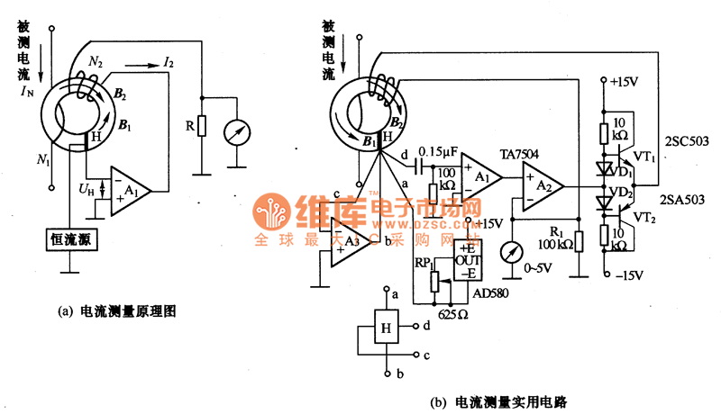
The figures (a) and (b) illustrate AC measuring circuits. Figure 21(a) presents a current measuring schematic diagram utilizing a magnetic balanced mode Hall device. When the magnetic field generated by the measured current, denoted as IN, is B1, this...
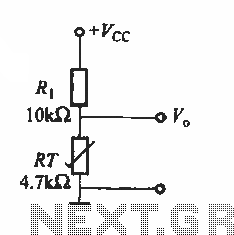
The basic application circuit for thermistors is illustrated. Figure (a) depicts a fundamental temperature measurement circuit. The accuracy of this temperature measurement is not high and is suitable only for applications with lower precision requirements. RT represents a positive...