
Rectification using a Gyrator Circuit

The described circuit employs a power supply configuration that minimizes output ripple by utilizing a combination of capacitors and a transistor following the rectification stage. Initially, a 470µF capacitor (C1) is connected post-rectification to smooth out the voltage fluctuations caused by the alternating current (AC) to direct current (DC) conversion. However, this value alone may not sufficiently reduce the ripple, especially under a load condition of 400mA.
To enhance the ripple suppression, the gyrator principle is employed, which leverages the current gain of a transistor—in this case, the 2N3055 power transistor. The gyrator acts as an effective capacitance multiplier. The capacitor C2, rated at 100µF, is placed at the output (Vreg) of the circuit. The effective capacitance at this node is significantly increased due to the transistor's current gain. Assuming a DC current gain (β) of 50 for the 2N3055, the output capacitance can be considered as being equivalent to a 5000µF capacitor. This multiplication of capacitance results in a much smoother voltage output, drastically reducing ripple.
The output from the rectifier exhibits approximately 5V peak-to-peak ripple when measured directly. However, by utilizing the emitter output of the 2N3055 transistor, the ripple is considerably lessened. This configuration allows the circuit to stabilize the output voltage more effectively, providing a cleaner DC supply to the load. The transient response of the circuit indicates that it may take several hundred milliseconds for the output voltage to stabilize after a load change or power-on condition, reflecting the time constant associated with the effective capacitance.
In summary, this circuit design efficiently reduces ripple in a power supply application by combining a rectifier, a strategically chosen capacitor, and a transistor utilizing the gyrator principle, resulting in a robust solution for powering heavy loads with minimal voltage fluctuation.To avoid excess ripple output on a power supply feeding a heavy load, usually a large value capacitor is chosen following the rectifier. In this circuit, C1 is only a 470uF capacitor. The gyrator principle uses the effect that the value of input capacitance at the base of a transitor is effectively multiplied by the current gain of the transistor.
Here C2 which is 100u appears at the ouput ( Vreg ) to be 100 x current gain of the 2N3055 power transistor. If you assume a dc current gain of 50, then the smoothing across the supply, would be as though you had chosen a 5000uF capacitor.
The load draws nearly 400mA. With the output directly from the rectifier there is about 5v pk-pk ripple in the output. Using the output at the emitter of the transistor things are much better. The circuit will take a few hundred milliseconds for the 🔗 External reference
Related Circuits
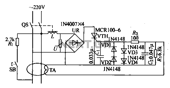
Current leakage protection is the most commonly used and effective leakage protection device. Current leakage protectors can be divided into electromagnetic and electronic types. The zero-sequence current transformer serves as the detection element, while electromagnetic leakage protection uses a...
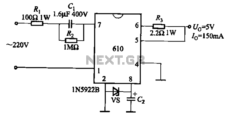
The AX610 Series has a maximum output current of 100 mA and features a scalable output current with an access regulator. The configuration includes two reverse polarity series regulators (2CW106, U: approximately 8.2V) as depicted in Figure (a). Figure...
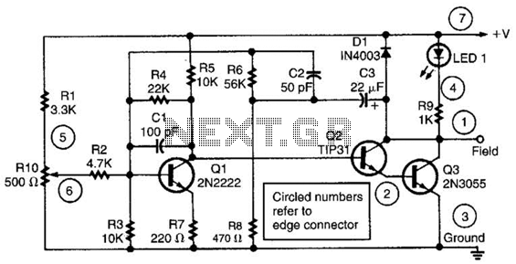
This alternator regulator utilizes a 3-transistor DC amplifier and is designed for a pulled-up field system, where one side of the alternator field returns to the +12V supply, and the other end is pulled toward ground. The circuit monitors...
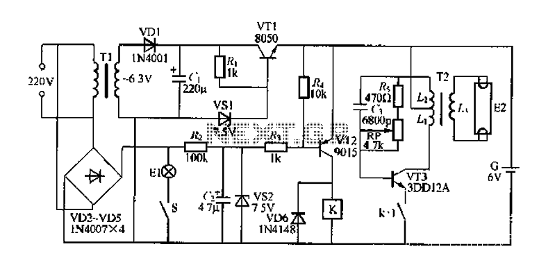
FIG. 284 illustrates a practical emergency power lighting system that activates automatically in the event of a sudden power outage. The fluorescent lights serve as emergency lighting. If the primary illumination lamp is turned off due to a power...
This is a simple function generator built around a single 8038 waveform generator IC. The circuit is capable of producing sine, square, or triangle waves within a frequency range of 20Hz to 200kHz. The function generator circuit utilizes the 8038...
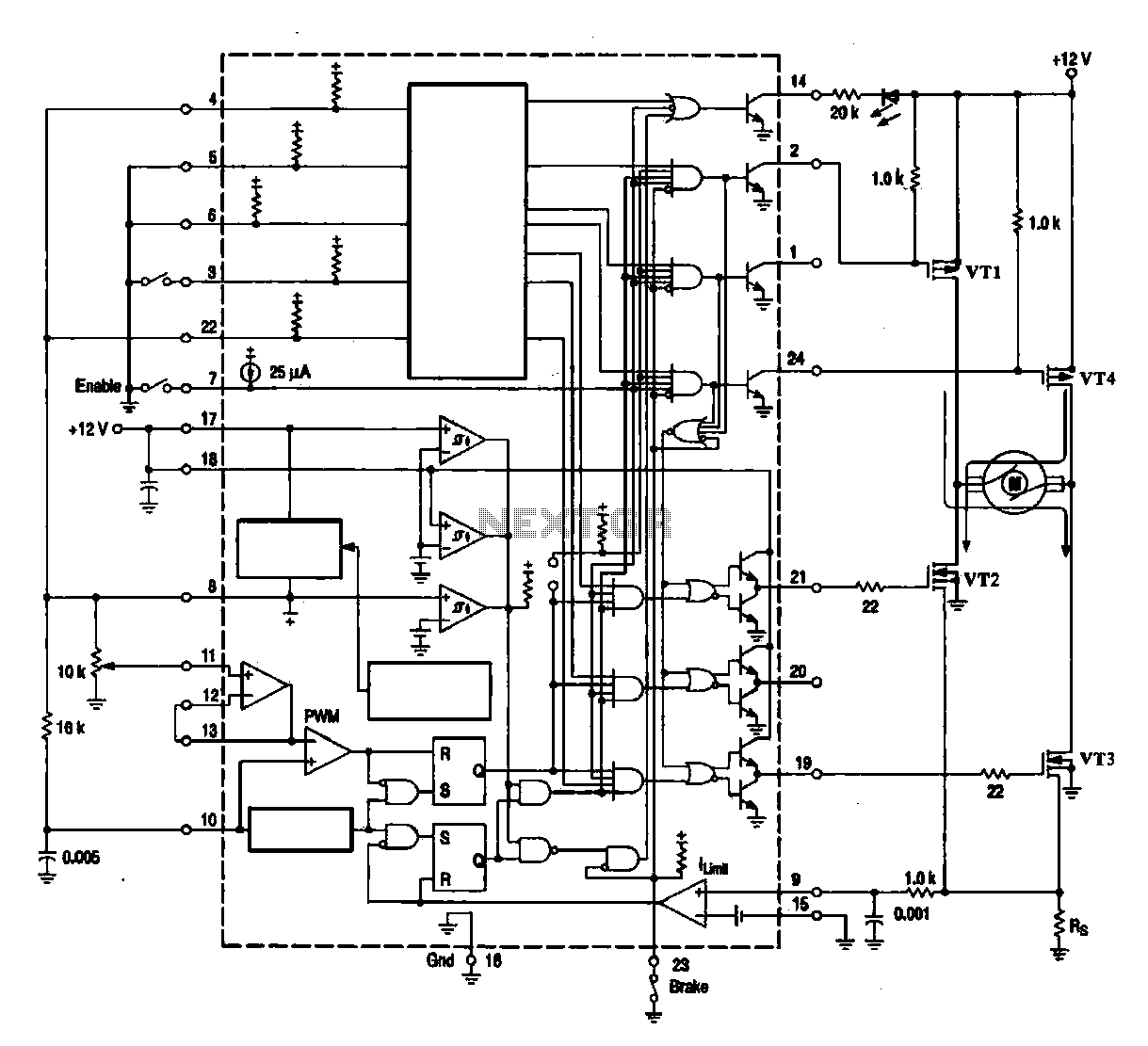
A DC brush motor driver circuit diagram utilizing the MC33035 chip is presented, illustrating a typical configuration for driving a straight DC brush motor. The circuit incorporates a field-effect transistor (FET) bridge driver setup. When transistor VT3 is activated,...