
AM reciever with MK484

More: This circuit was assembled to evaluate the MK-484 as a possible remote control/data receiver for the 1600-1750 meter band. The on-off switch is hardly necessary due to the low current draw of the circuit, but there is potential for adding more circuitry later.
When listening to the AM (MW) band, considerable electromagnetic interference (EMI) can be heard; however, when switched to the longwave band (LW), the EMI disappears. This observation aligns with the datasheet indicating a significant drop in sensitivity at LW frequencies compared to MW frequencies. The MK-484 performs adequately as a receiver or intermediate frequency (IF) around 1 MHz but exhibits reduced sensitivity at 180 kHz, which may limit its application to very short-range scenarios.
The cutoff frequency of the output RC network is set at 1.6 kHz.
Testing of the receiver was conducted with a 187 kHz RF source, which was the first application for the MK-484. The necessary components, including the ferrite coil, tuning capacitor, and KM-484, were sourced from Peter Crowcroft's Kitsrus.com website. A high-impedance earphone was obtained from Bahnmo Plaza, an electronics market in Bangkok.
The gain of the circuit is influenced by the collector current and output voltage, indicating that the amplifier is inherently nonlinear. The gain is independent of the collector resistor value when the only load on the collector is the load resistor (no earphone), as the collector current and gain vary with the collector load resistance, effectively canceling the resistance change effects, assuming stable collector voltage.
With a battery voltage of 1.62 volts, the collector voltage measures 0.89 volts, resulting in a voltage of 0.73 volts across the collector load resistor. The maximum open-loop gain is calculated to be approximately 27.7, corresponding to 20 log (38 x 0.73) = 28.8 dB, which is the gain measurement when no earphone is connected.
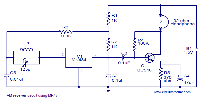
When a 2k Ohm earphone is used, the collector impedance drops to 667 Ohms, thereby reducing the gain proportionally to 667/1k x 27.7 = 18. The 56k Ohm resistor, while significant in the circuit, can be overlooked as long as it is much larger than the collector load resistor. However, increasing its value while decreasing the transistor's beta can lead to higher output voltage and reduced gain. The selected value strikes a balance between collector impedance and maintaining an appropriate collector voltage. A zero-ohm resistor would yield a collector voltage of approximately one base-emitter drop (about 0.6 volts).The basic MK484 (Replacement for the ZN414) connected in its minimum configuration as a radio receiver for the A.M. Broadcast band and the upper half of the United States' FCC Part 15 Lowfer (1600-1750 meter) band. Its a circuit straight out of the application note and I have fount it to be useful on the bench. Even more convenient that using the Radio Shack short wave receiver, mainly because the tuning is so broad on this that I don't have to tune precisely to hear the signal.
I put this together to evaluate the MK-484 as a possible remote control/data receiver for the 1600-1750 meter band. The on-off switch is hardly necessary because of the low current draw of the circuit, but one never knows if one is going to add more circuitry later.
When listening to the AM (MW) band, there is a lot of EMI to be heard, but went it is switched to the longwave band (LW), the EMI disappears. This agrees with the datasheet showing sensitivity dropping off quite a bit a the LW frequencies compared to the MW frequencies.
This chip would certainly be a nice receiver or IF around 1 MHz but seems to come up short in the sensitivity departmentat 180 kHz. Still, it might come in handy for some very short range applications. The cutoff frequency of the output RC is 1.6 kHz. I tested the receiver with the 187 Khz RF Source also mentioned on this site. Indeed, checking out the MK-484 was the first use of the 187 khZ RF Source. I had acquired the radio parts - the ferrite coil, tuning cap, and the KM-484 from Peter Crowcroft's Kitsrus.com web site on the component sales page (http://www.kitsrus.com/bits.html).
As for the high impedance earphone, I found that in Bahnmo Plaza, and electronic components market in Bangkok. You are on your own as far as finding one elsewhere.This expression is approximately correct at room temperature, and the gain varies directly with absolute temperature, assuming the collector load impedance and collector voltage are stable.
If you look at this expression long enough, you'll realize a few of things: The gain is a function of collector current, and therefore output voltage, meaning that this amplifier is inherently nonlinear. Another thing is that is the only load on the collector is the load resistor (no earphone) then the gain is independent of the value of the collector resistor -this is because the collector current, and therefore the gain, varies as a function of the collector load resistance, thereby canceling the effects of the resistance change, assuming that the collector voltage remains the same.
The gain works out to about 38 x the number of volts across the collector load resistor. In this circuit, with a batter voltage of 1.62 volts, the collector voltage is 0.89 volts, meaning that the voltage across the collector load resistor is 0.73 volts, so the maximum open loop gain is approximately 38 X 0.73 = 27.7, which also works out to 20 log (38 X 0.73) = 28.8 db (if you like to see gain numbers in db). The maximum open loop gain occurs when there is no earphone connected. When used with a 2k Ohm earphone, the collector impedance is 667 Ohms, so the gain is reduced proportionally, to 667/1k X 27.7 = 18.
The number "1k" is the value of the resistor load resistor and determines the collector current. I glossed over the 56k resistor. As long as this resistor is large compared to the collector load resistor it can be ignored as part of the collector load, but the larger it is, and the lower the transistor's beta, the higher the stage's output voltage, and the lower the gain. The value I used here seems to be a good balance between affecting the collector impedance and letting the collector voltage get too high.
In the limit, a zero ohm resistor would result in a collector voltage of one base-emitter drop (about 0.6 volts). 🔗 External reference
Related Circuits
This 1 channel infrared transmitter/receiver remote control is the cheapest and simplest you can find. The transmitter transmits a sequence of pulses on 36 KHz frequency carrier. The diodes are Schottky type because of their low voltage drop (only...
This receptor is born of our annoyance against the irritating problem of Quartz: With the RX21, completed research of cut crystal for your personal rating, you have with him, access to ALL band frequencies, in steps of 5 kHz!...
A cost-effective and straightforward AM receiver circuit utilizing the MK484 integrated circuit. The circuit requires minimal external components and operates within a frequency range of 150 kHz to 3 MHz. The MK484 AM receiver circuit is designed for simplicity and...
This circuit was designed to control a 32 channel Christmas light show from the PC serial port. Originally designed with TTL logic, it has been simplified using CMOS circuits to reduce component count. It is a fairly simple, reliable...
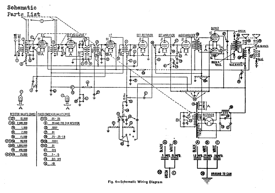
The Philco radio is a nine tube superheterodyne receiver combining standard broadcast, police and airplane reception and employs the high efficiency 6.3 volt filament tubes, automatic volume control, bass compensating tone control, shadow tuning and push pull pentode output. The...
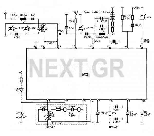
This receiver utilizes the TDA1072A, a complete AM receiver integrated circuit that requires relatively few peripheral components to create a high-quality AM radio circuit. Unlike other AM radio integrated circuits, it employs a minimal number of external tuned inductors...