
MK484 AM receiver circuit

The MK484 AM receiver circuit is designed for simplicity and affordability, making it suitable for educational purposes and hobbyist projects. The primary component, the MK484 IC, is a low-power AM radio receiver chip that integrates various functions necessary for AM signal processing.
The circuit typically includes a few essential external components: an antenna for signal reception, a variable capacitor for tuning, and a few resistors and capacitors for biasing and filtering. The antenna captures the AM radio waves, which are then fed into the MK484. The integrated circuit amplifies the received signals and demodulates them, allowing for audio output.
The frequency range of 150 kHz to 3 MHz covers the lower end of the AM broadcast band, enabling reception of various AM stations. To optimize performance, the circuit may include a simple audio output stage, such as a small speaker or headphone jack, connected to the output pin of the MK484.
Power supply requirements for the MK484 are modest, typically operating within a range of 3V to 9V. This allows for the use of standard batteries or low-voltage power supplies. The circuit's simplicity and low component count make it an excellent choice for those new to electronics, providing an opportunity to learn about radio frequency principles and circuit design.
Overall, the MK484 AM receiver circuit exemplifies an effective blend of simplicity and functionality, making it accessible for a wide range of users interested in radio technology.A very cheap and simple AM receiver circuit using IC MK484. The circuit requires fewexternal components and has a frequency range from 150KHz to 3MHz.. 🔗 External reference
Related Circuits

This device utilizes the MC145026/MC145027 encoding and decoding circuit along with the TDA1808/TDA1809 RF transmitter/receiver module. It can be operated flexibly within a range of 10 to 120 meters, allowing users to maintain the original external appearance and internal...

The LM10 integrated circuit (IC) is utilized due to its reference voltage feature, which is advantageous for DC power supply applications. By employing two LM10 ICs, different output voltages and current levels can be achieved. This circuit includes short-circuit...
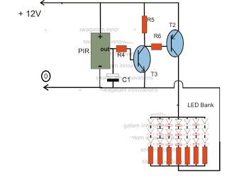
The circuit is an LED driver that responds to ambient light as well as the presence of an intruder, varying its illumination accordingly. Additionally, it includes an ambient light sensor to turn the LEDs on and off, and a...

This simple wind charger circuit project is designed using the LTC1042 monolithic CMOS window comparator, manufactured by Linear Technology. The wind charger circuit utilizes wind power to generate the energy necessary for charging Ni-Cd or lead-acid batteries. When the...

The following circuit illustrates a Bass and Treble Controller Circuit. This circuit is constructed based on the classic Baxandall tone control circuitry. The Bass and Treble Controller Circuit is designed to adjust the low and high-frequency response of audio signals,...
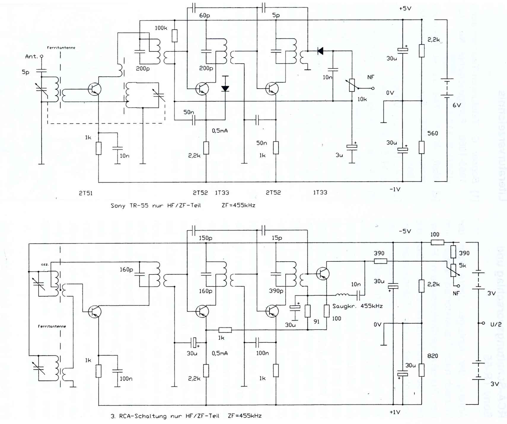
The circuitry of the Regency exhibits several unique characteristics. Notable features include the self-oscillating mixer stage, the base bias voltage of the second IF stage derived from the AF power stage, an unusual IF frequency of 262 kHz, and...