
Amp Monoblock UL
The amplifier design described employs a sophisticated approach to tube amplification, leveraging the characteristics of EL34 tubes in an ultra-linear configuration to optimize performance while minimizing distortion. The push-pull parallel arrangement effectively reduces load resistance, which enhances power output and maintains audio fidelity. The elimination of global feedback indicates a design philosophy prioritizing simplicity and direct signal path integrity, which can contribute to a more natural sound reproduction.
The use of a regulated power supply ensures stable operation under varying load conditions, which is crucial for maintaining audio quality, especially in high-power applications. The gain block configuration allows for flexibility in matching the amplifier with various preamp outputs, enhancing compatibility with different audio sources. The long tail pair design, coupled with a current sink, allows for improved linearity and reduced distortion, which is essential in high-fidelity audio applications.
Careful consideration has been given to component selection, including the choice of resistors to prevent oscillation and the use of capacitors to protect against inductive spikes. This attention to detail reflects a thorough understanding of the challenges involved in tube amplifier design and the need for robust circuit protection measures.
Overall, this amplifier design represents a well-considered approach to achieving high-quality audio amplification with vacuum tubes, balancing power, distortion, and circuit simplicity. The schematic diagram serves as a foundational reference for further development and testing, ensuring that the final product meets the desired performance criteria.You may be wondering why I am using four tubes. The reason is to get 50 watts without pushing them right to their limit. My tube manual gives two setups for EL34s in ultra linear. Both require a 6 k ohm transformer. Both setups use exactly the same voltages but one says you get 20 watts at 0. 34 percent distortion and the other says you get 34 watts at 2. 5 percent distortion. The applied voltages are the same except for the AF grid drive voltage. They are just driving them harder to get more power and more distortion. Connecting four tubes in push-pull parallel lowers the load resistance to 3 k, which almost matches a transformer I have already bought, and gives more power with not a lot of distortion. I could almost live with it with no global feedback. I don`t know how Eico got 50 watts with two tubes but it is likely I am remembering it wrong and they were actually 35 watt amplifiers.
See farther down this page. This is the amplifier I`m going to build. The tube manual data is for cathode bias so I`m going to see if I can`t simplify the circuit. The screen voltage regulator is already gone and if I can eliminate the negative voltage supply I`ll have a really good circuit. I`ll post it under its own heading on the front page when it is finished. Because of the extremely low powers at the low frequency end, from the Hammond transformer, I measured the distortion at various frequencies at 12.
5 watts (6 dB below maximum rated power. There is no reason to do the same for the Edcor. Distortion in the bass is readily apparent because all of the harmonics are in the range of a speaker to reproduce. Also most of the power in pop music is in the bass end. Just think of those cars with subwoofers that rattle the windows in your house as they drive by. Even in jazz or classical, there is a lot of power in the bass. Therefore if the power is going to roll-off at one end, it is best to have it drop off at the high end rather than the low.
Here is the schematic diagram of the final version of the amplifier. I have not constructed it in a permanent form and I don`t know if I ever will. I want to test these Edcor transformers with a pair of EL34s before I decide what to build for my own listening pleasure. I tested the circuit using my regulated power supply for the main B+. Also I didn`t test the optional 12AX7 gain block. The amplifier without this gain block requires 10. 8 volts RMS to drive it to full power. If your pre-amp has enough output you can eliminate this stage. The amplifier begins with the low distortion gain block set to a gain of 10. 1. Then the long tail pair with a 6BH6 current sink in the cathodes of the two triodes. Signal is fed to the left hand triode and negative feedback to the right hand one. Signal is coupled from the plates of the long tail pair to the 6SN7 cathode follower which is directly coupled to the grids of the 6L6s.
The 1 k ohm resistors are to ensure that the 6L6s will not oscillate. The 100 ohm resistors in the screen grids are to suppress oscillation that set in as soon as the ultra linear taps were connected. The Hammond output transformer is wired for 8 ohms and although not shown is terminated with an 8 ohm 100 watt resistor for test purposes.
The power supply has a feature which should be there but a generational disconnect has caused the reason to be forgotten. When the power switch is turned off sometimes an inductive spike is generated which is several times the normal peak output of the secondary winding.
Vacuum diodes were not troubled by this spike but solid state ones can be burned out. The capacitor across the secondary is meant to suppress this spike. I used a. 002 uf 6 kV because I have some on hand. I would recommend use of a. 005 uf 3 kV available from RF Parts. The price isn`t out of line for vacuum tube parts these days. I know this capacitor is necessary because I burned out a diode while testing the power supply on t 🔗 External reference
Related Circuits
The linear charging ramp is particularly beneficial in applications requiring precise linear voltage control. Potential uses include a prolonged voltage-controlled timer, a voltage-to-pulse-width converter, or a linear pulse-width modulator. Q1 functions as the current source transistor, delivering a constant...
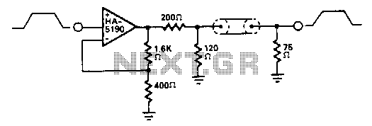
The HA-5190 can drive the 75-ohm coaxial cable with signals up to 2.5 V peak-to-peak without the need for current boosting. In this circuit, the overall gain is approximately unity due to the impedance matching network. The HA-5190 is a...
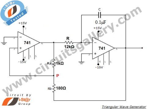
An operational amplifier-based triangular waveform generator is a simple circuit that is widely used in function generators. This circuit utilizes the 741 operational amplifier to create a triangular wave generator. The output waveform of an integrator will be triangular...
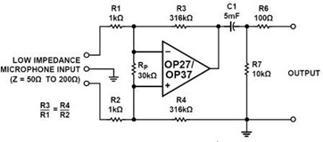
A simple but effective fixed gain transformerless microphone preamplifier circuit diagram is shown in the picture below. The circuit amplifies differential signals from low impedance microphones by 50 dB and has an input impedance of 2 kOhms. The OP27/37...
The example below illustrates the use of an operational amplifier (op-amp) as an audio amplifier in a basic intercom system. A small 8-ohm speaker is utilized as a microphone, which is connected to the op-amp input through a 0.1...
Turns off your amplifier when idle for 15 minutes. Fed by amplifier tape-output. This circuit turns off an amplifier or any other device when a low-level audio signal fed to its input is absent for 15 minutes at least....