
Amplifier Timer

This circuit is designed to automatically turn off an amplifier or any connected device after a specified period of inactivity, specifically when no audio signal is detected for 15 minutes. The circuit is powered through the tape output of the amplifier, ensuring that it operates only when the amplifier is active.
The core of the circuit involves two operational amplifiers (IC2A and IC2B) that serve to amplify and square the low-level audio signal received at the input. This amplification is crucial for ensuring that even weak signals can be detected reliably. The output of these operational amplifiers is monitored by an LED (D4), which provides a visual indication of signal presence. When the LED is illuminated, it indicates that an audio signal is being processed, and this state is used to reset the timing mechanism of the circuit.
The timing function is managed by a timer IC (IC3), which begins counting when no audio signal is detected. The timer is designed to count for a duration of 15 minutes. During this period, pin 2 of IC3 remains low, which keeps two transistors (Q1 and Q2) in a conducting state. This allows current to flow through the relay, keeping it activated and thus maintaining power to the connected appliances through connector SK1.
If the audio signal is absent for the full 15-minute duration, IC3 will trigger pin 2 to go high, which turns off the transistors Q1 and Q2, subsequently deactivating the relay. This action completely cuts power to the connected devices, effectively turning them off and conserving energy.
Additional components such as capacitor C5 and resistor R9 may be utilized in the circuit to stabilize the operation of the timer and prevent false triggering due to noise or transient signals. The design ensures that the amplifier and any associated devices remain operational during active use but are automatically powered down during periods of inactivity, enhancing energy efficiency and prolonging the lifespan of the equipment.Turns-off your amplifier when idle for 15 minutes Fed by amplifier tape-output. This circuit turns-off an amplifier or any other device when a low level audio signal fed to its input is absent for 15 minutes at least. Pushing P1 the device is switched-on feeding any appliance connected to SK1. Input audio signal is boosted and squared by IC2A & IC2B and monitored by LED D4. When D4 illuminates, albeit for a very short peak, IC3 is reset and restarts its counting. Pin 2 of IC3 remains in the low state, the two transistors are on and the relay operates. When, after a 15 minutes delay, no signal appeared at the input, IC3 ends its counting and pin 2 goes high. Q1 & Q2 stop conducting and the relay switches-off. The device is thus completely off as also are the appliances connected to SK1. C5 & R9 🔗 External reference
Related Circuits
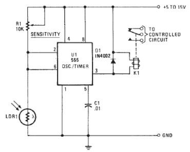
The following circuit illustrates a Photo Alarm Electronic Circuit. This circuit is based on the 555 Timer IC and incorporates features such as an LDR (light-dependent resistor). The Photo Alarm Electronic Circuit utilizes a 555 Timer IC configured in monostable...
It is unlikely that the device was designed to be powered by a 9V battery, as they are not very robust. The battery life is typically under 2 hours when using an alkaline battery. The power requirements of electronic devices...
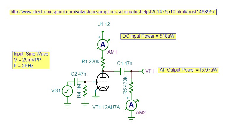
The circuit presented is experimental and should provide some fun to build and play about with. It has been built and tested and works very well indeed. Please note that it is a low current Class-A opamp and is...
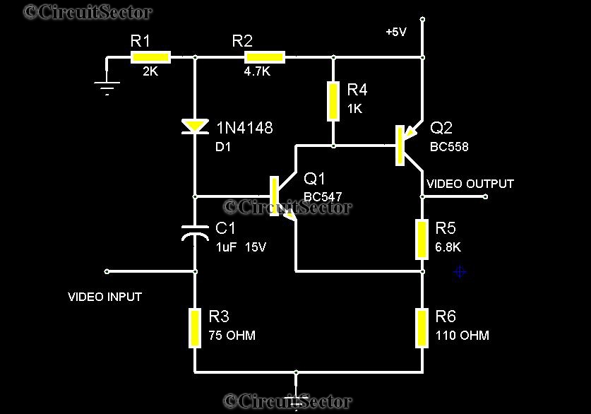
There are instances when it is necessary to view video clips captured by a digital camera on a television. This can be accomplished by connecting the camera's video output to the television's video input. However, a direct connection is...
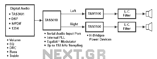
A digital amplifier is a new device that IC manufacturers are eager to capitalize on, leading to the launch of unique digital amplifier products. Below are brief descriptions of some representative devices. The TA2022, produced by Tripath, is an...
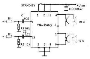
This car audio amplifier provides an output of 40 watts when connected to a 2-ohm speaker. The amplifier circuit delivers a power output of 40 watts per channel at a 2-ohm load and 22 watts at a 4-ohm load....