
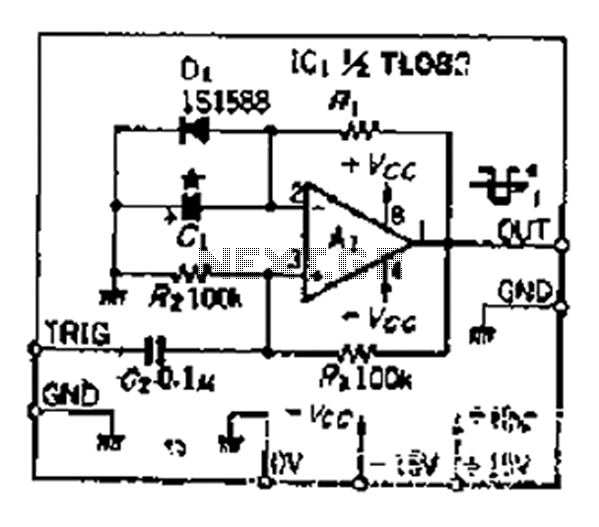
Amplifier input signal overdrive auto-protection

The described circuit functions as a protective mechanism for signals that exceed the standard operational threshold before reaching an amplifier. The key component utilized in this design is a transistor, which serves as a substitute for the more traditional zener diode. This substitution is significant as it allows the circuit to effectively manage higher input voltages, specifically those above 1 volt r.m.s., without introducing distortion to the signal.
The circuit's design is notably efficient, as it minimizes the component count by eliminating the need for additional elements such as potentiometers and voltage dividers. This simplification not only reduces the complexity of the circuit but also enhances reliability by decreasing the number of potential points of failure.
The performance specifications indicate that the circuit maintains a total harmonic distortion (THD) of 0% at output levels up to 700mV r.m.s. This is a critical parameter for audio applications, as it ensures that the output signal remains true to the input signal within this range. For output levels exceeding 700mV r.m.s. and approaching 1V r.m.s., the total harmonic distortion is still impressively low at 0.02%. This level of distortion is acceptable for high-fidelity applications, ensuring that the integrity of the audio signal is preserved even at higher levels.
In summary, this circuit is designed to protect amplifiers from overdriven signals while ensuring minimal distortion, thereby providing an effective solution for audio signal management. The use of a transistor not only simplifies the design but also enhances the performance characteristics of the circuit.That circuit protects the overdriven signals going into an amplifier. Instead of a zener diode we use a transistor. That way we ensure that the above the ordinary input voltages ( 1 volt r.m.s.) can be acheaved without distortion. Also the use of a transistor limits the number of components used in this schematic. You don't need any potentiometers or voltage dividers. The total distortion at the output until 700mV r.m.s. is 0%. Above that until 1V r.m.s. the total harmonic distortion can be 0.02%.
Related Circuits
This design is based on an 18 Watt Audio Amplifier and was developed primarily to address the needs of users who have difficulty locating the TLE2141C chip. It utilizes the commonly available NE5532 Dual IC; however, its power output...
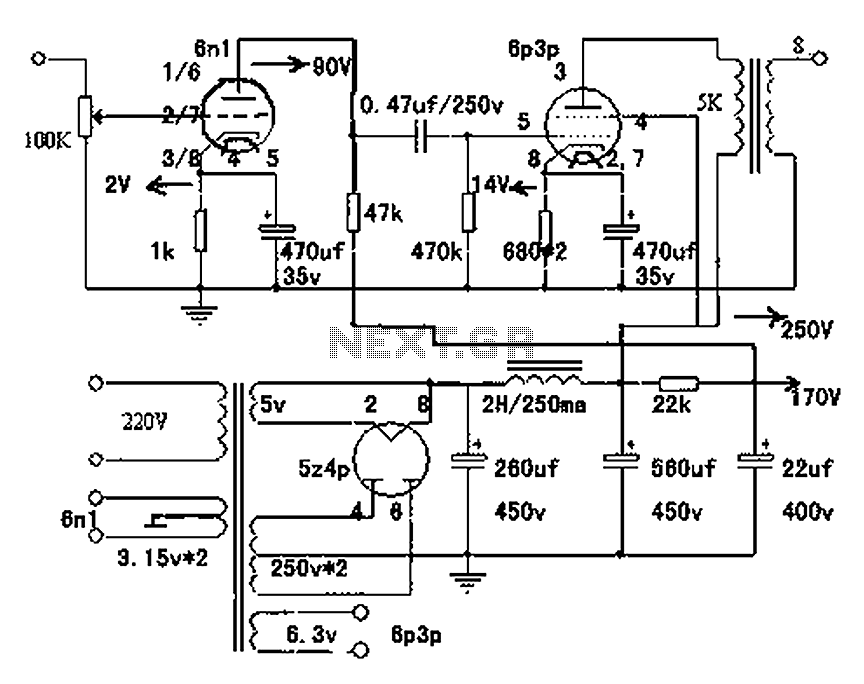
The following diagram is the circuit diagram of a 20W power amplifier built using the tube component EL34. The EL34 is a well-known tube, ideal for power tube amplifiers. The circuit presented is a complete design that includes both...
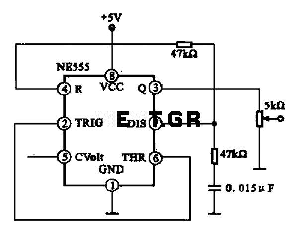
A 1 kHz square wave signal generator is created using a time base circuit with an NE555 timer, combined with a time constant circuit consisting of a 47 kΩ resistor and a 0.15 µF capacitor. The circuit utilizes the...
Electronic tube amplifier enthusiasts consider a simple, high-quality single-ended Class A circuit to be an ideal starting point. This single-ended Class A tube amplifier is known for its warm sound and high success rate. The article outlines the use...
Although people believe that using a timer with an operational amplifier (op-amp) does not yield significant results, it can still be advantageous in certain scenarios. In environments with high noise levels, the application retains its benefits. When the phase...
A simple and effective antenna amplifier can be built using the provided circuit diagram. This amplifier is designed for the frequency range of 35 kHz to 150 MHz. It utilizes transistors, offering a low non-linearity of 3 dB and...