
Amplifier Stages

The design and implementation of audio connectors and amplifiers require careful consideration of various electrical parameters and physical characteristics. The use of XLR connectors, while more durable, necessitates an understanding of their limitations, particularly regarding switch contacts essential for channel selection. The input resistance configurations in amplifiers influence the overall audio quality and tonal characteristics, necessitating precise calculations and component selections to achieve desired outcomes. The integration of bypass capacitors and their voltage ratings plays a critical role in the performance of audio circuits, as improper ratings can lead to inefficiencies and potential failures. Additionally, grounding techniques, particularly in valve amplifiers, must be meticulously planned to prevent interference and ensure optimal signal integrity. The choice of shielding for preamp valves is equally important, as it protects against unwanted noise and enhances the reliability of the amplifier's performance. Overall, a comprehensive understanding of these elements is vital for the effective design and operation of audio equipment.The XLR or Cannon-type connector is clearly a better audio connector than a 6. 5mm jack plug and socket, but tradition makes the 6. 5mm socket mandatory despite its serious connection problems. Inputs range from a single socket connected directly to the grid of the first stage, no resistors or blocking cap (Marshall PA); and up to six ( Vox AC-30 II), all different. When the input is plugged into the upper socket the input has 1M to ground and two 68k in parallel, 34k, in series. In the lower input the input resistance is two 68k in series, 136k, and divides the input in half (-6dB). The cathode bypass capacitor on the lead channel is much lower value, 0. 67 uF, causing more AC negative feedback across the 2k7 at lower frequencies, so producing a `toppy` channel.
The outputs are mixed downstream. Ideally the common of the socket should be isolated from the chassis to prevent earth loops. Commonly available isolated sockets are not nearly robust enough for guitar input service. XLR`s are tougher, but they don`t come with switch contacts. Simple amps have only one amplifier channel even when they have a lot of input sockets. Different signals are mixed early in the chain and amplified together. More complex amplifiers provide two or more channels. Normally they were an un-effected channel with its own tone and volume controls; and an effected channel with its own controls including reverb and tremolo/vibrato. These were then mixed into the main power amplifier. There is no reason why channel switching cannot be applied to a valve amp if desired, but it is important to have an `at-a-glance` indicator to show you which channel is selected.
The anode and cathode resistors are typically 100k and 1k5 as shown, or 220k and 2k2, always with a 25uF/25V bypass. This was not a great choice since they only have around 2 volts on them in operation. Failures may be rare but they may not be bypassing audio to their best either. There may be some benefit from using a voltage rating closer to the actual operating voltage. As a rule of thumb electros should operate at more than half their rated voltage so they `form up` correctly.
The value tolerance on typical electros of the era, for example Elna, was -50%/+100%. The EF86 shown here was a specific low-noise front-end amp, but other pentodes such as the 6AU6 have been used. A pentode provides considerably more voltage gain than a single triode stage e. g. x200 against x50. The single-point earth was literal with these stages, all earth returns brought back to a single common point near the valve base, sometimes a metal cylinder in the middle of the valve base.
Octal sockets sometimes had four inviting grounding lugs formed into the base mounting ring with the same general idea, but generally not as effective (particuarly at RF). The HT supply should mirror the grounding and should also be single-point, the two ends of the 24uF bypass cap being the two common points, hopefully shorted together to AC by the cap.
In PA mic preamp service these were sometimes mounted on a sub-chassis, in cages and sometimes boxes, floating and insulated with rubber grommet shock mounts to prevent microphony. Preamp valves are prone to microphonics, Radio Frequency rectification, capacitive pickup, and magnetic pickup, so are normally fitted with some form of shielding can.
This ranges from a simple curl of aluminium with a wire clip retainer, to lock-down blackened steel with internal seating spring and copper heat transfer fingers. The two most common forms are i) a twist-lock like an inside-out lightglobe bayonet connector, and ii) a snap-on form with a constriction around the bottom that snaps over a matching rib
🔗 External reference
Related Circuits
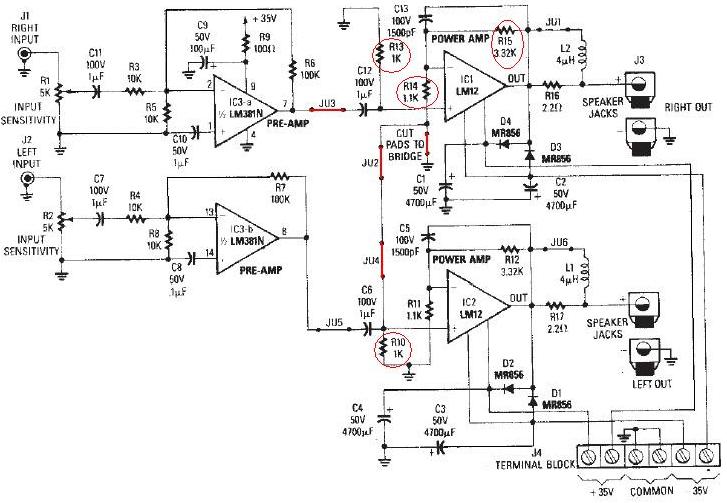
The LM12 audio amplifier circuit is designed to deliver high output power for 8 ohm or 4 ohm load impedances. The maximum output power provided by the LM12 audio amplifier is approximately 60 watts for a 4 ohm load...
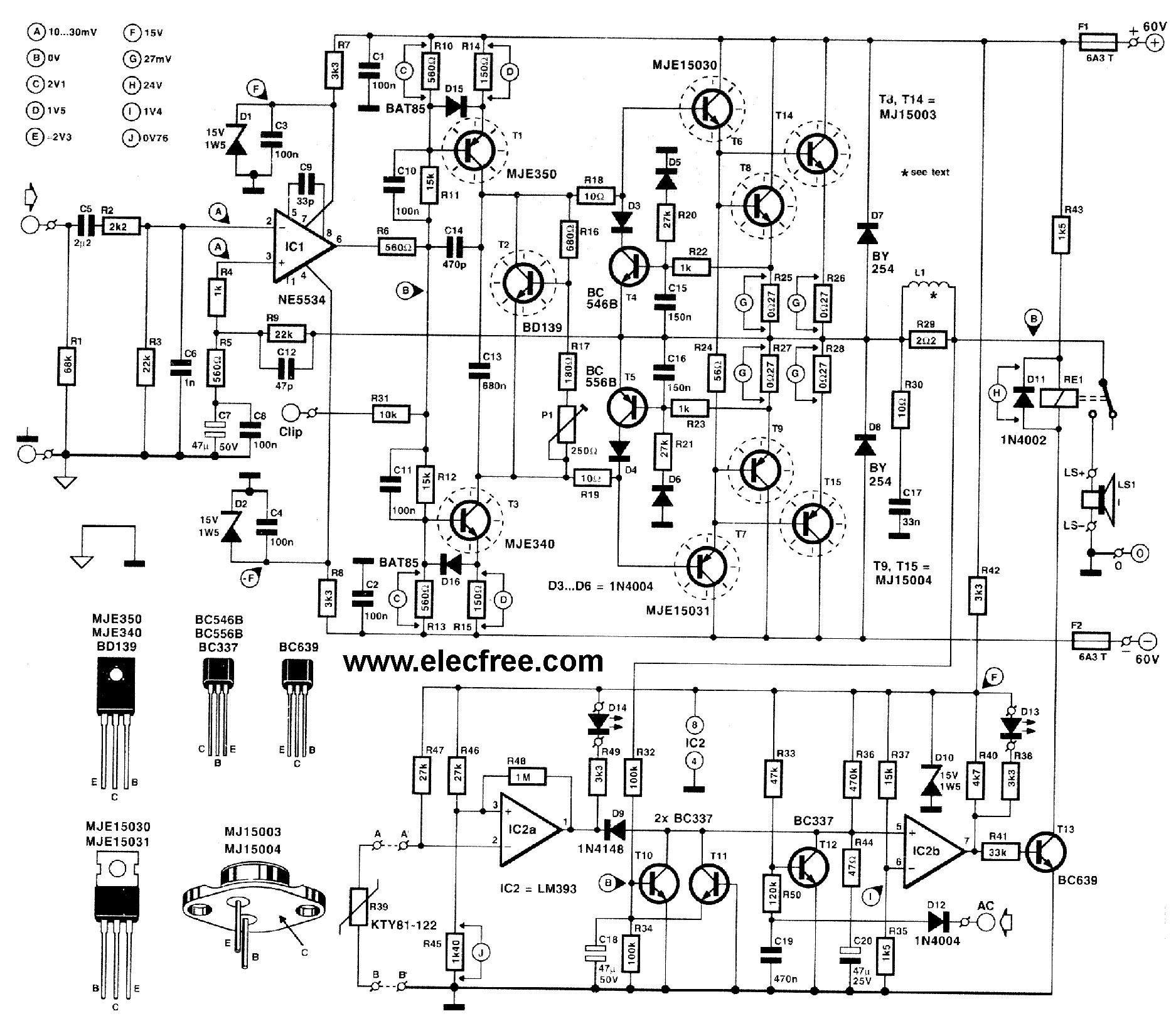
This circuit is designed for friends who are interested in high-power amplifier circuits. It can deliver approximately 300 Watts RMS and operates as an OCL (Output Capacitor-Less) Class AB amplifier, providing high sound power while systematically protecting the loudspeaker...
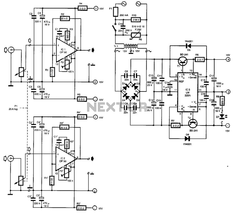
Built around Precision Monolithics Inc. OP-50 operational amplifiers, this amplifier is capable of driving 100- to 14-ohm headphones. It maintains a flat frequency response within 0.4 dB from 10 Hz to 20 kHz and exhibits a total harmonic distortion...
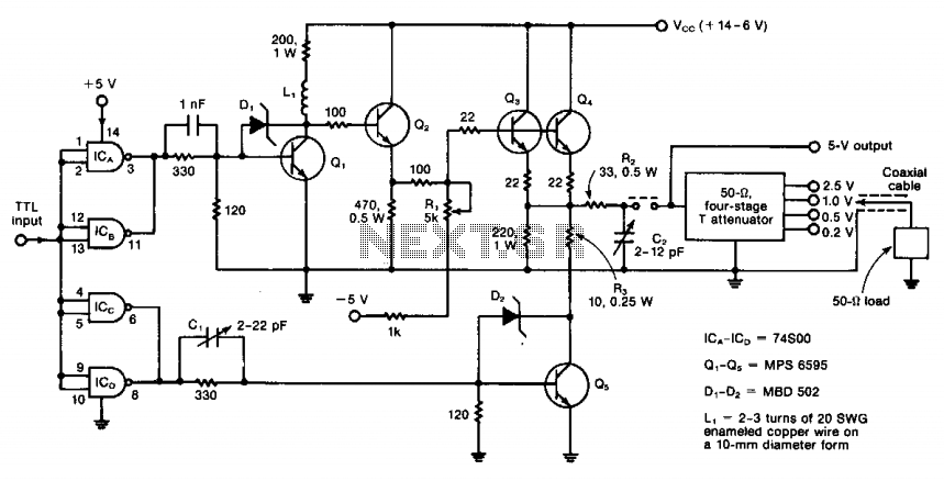
The circuit operates from DC to 50 MHz and is capable of delivering pulses as short as 10 ns. It is driven by a TTL signal through a 740S00 quad Schottky NAND gate, with input connections made via ICA...
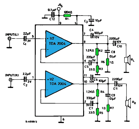
The TDA2004 integrated circuit (IC) is a popular choice among audio electronics enthusiasts due to its affordability and availability. This IC is often utilized in audio amplifier designs because it features two outputs and inputs, making it easy to...
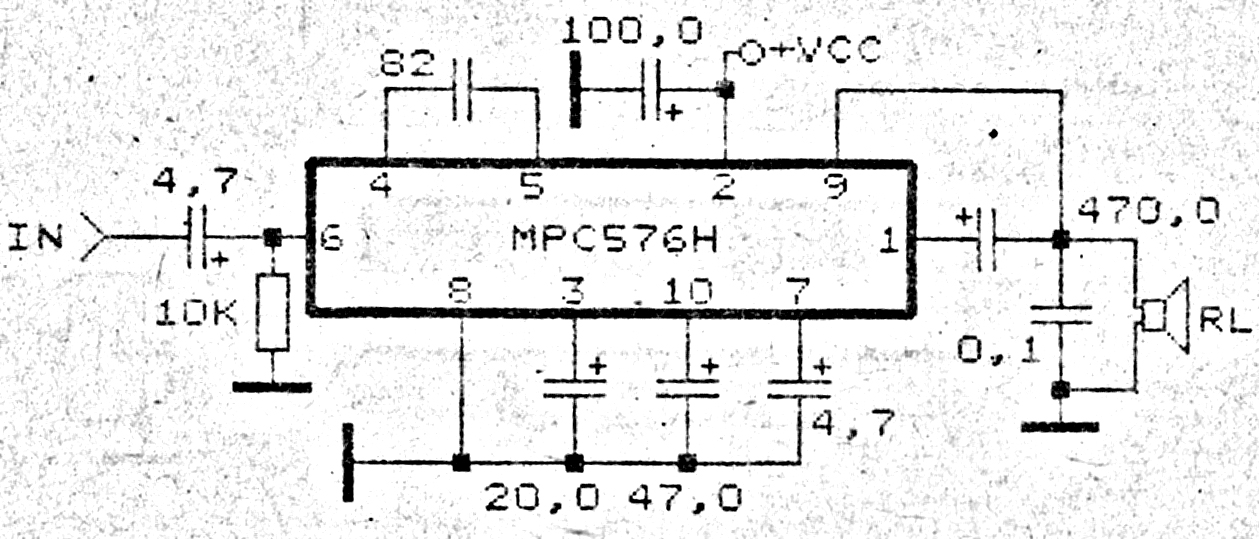
This amplifier circuit exhibits good sound quality. Although it does not provide high output power, it is capable of producing both soft and loud sounds reliably. The circuit utilizes a single IC, the MPC576H, along with several supporting components....