
Amplifier Timer

This circuit operates as an automatic audio signal detector and relay controller. It is designed to monitor audio signals and manage power to connected devices based on the presence or absence of these signals. The circuit begins its operation when the user presses switch P1, which activates the system and allows power to flow to the output terminal SK1.
The core of the circuit utilizes operational amplifiers IC2A and IC2B to amplify and square the incoming audio signal, ensuring that even low-level signals can be effectively processed. The output of this amplification is visually indicated by LED D4, which serves as a status indicator for the presence of an audio signal. When the audio signal is detected, even momentarily, the capacitor C3 is reset, which restarts the timing sequence necessary for the circuit's operation.
The timing mechanism is controlled by integrated circuit IC3. Under normal conditions, pin 2 of IC3 remains low, which keeps transistors Q1 and Q2 conducting. This allows the relay to remain activated, thus maintaining power to SK1 and any connected devices. However, if the audio signal is absent for 15 minutes, IC3 will conclude its timing sequence, causing pin 2 to transition to a high state. This transition turns off transistors Q1 and Q2, resulting in the relay deactivating and cutting power to the connected devices.
Additional components C5 and R9 ensure that IC3 is properly reset when the circuit is powered on, providing reliable operation from the start. The inclusion of switch P2 allows the user to manually turn off the device at any time, providing flexibility in operation. This circuit design is particularly useful in applications where automatic power management based on audio signal detection is desired, enhancing energy efficiency and device longevity.This circuit turns-off an amplifier or any other device when a low level audio signal fed to its input is absent for 15 minutes at least. Pushing P1 the device is switched-on feeding any appliance connected to SK1. Input audio signal is boosted and squared by IC2A & IC2B and monitored by LED D4. When D4 illuminates, albeit for a very short peak, I C3 is reset and restarts its counting. Pin 2 of IC3 remains in the low state, the two transistors are on and the relay operates. When, after a 15 minutes delay, no signal appeared at the input, IC3 ends its counting and pin 2 goes high. Q1 & Q2 stop conducting and the relay switches-off. The device is thus completely off as also are the appliances connected to SK1. C5 & R9 reset IC3 at power-on. P2 allows switch-off at any moment. 🔗 External reference
Related Circuits
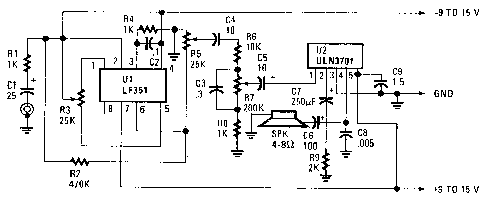
The FET operational amplifier (op amp) requires a bipolar voltage at pins 4 and 7, with a common ground to achieve optimum gain. The gain can be calculated by dividing R2 by R1. Zero-set balance can be achieved through...
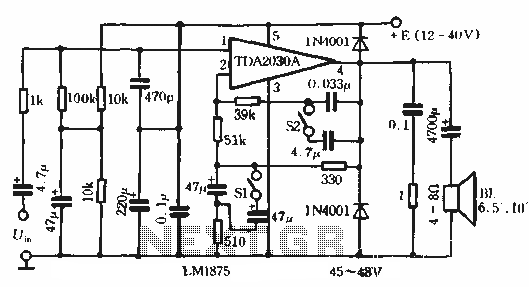
This circuit features bass boost compensation for a practical power amplifier. It is important to adhere to the specified parameters of the amplifier circuit elements. When switches S1 and S2 are disconnected, the bass boost function can be set...
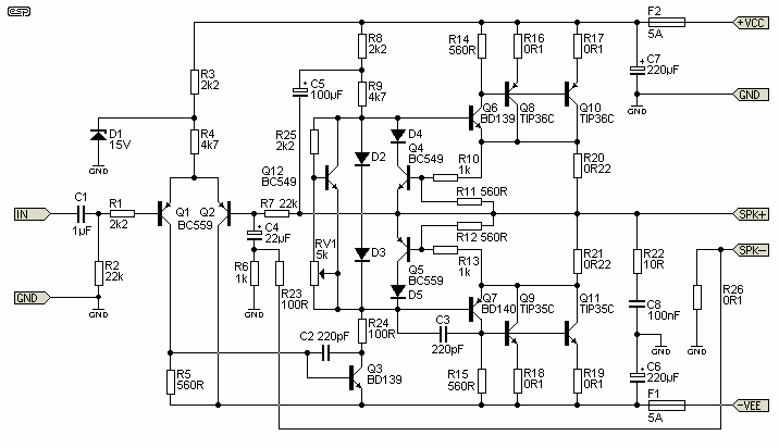
The ability amplifier has remained functional since it was first introduced in 2002. It is not broken, so there is no reason to fix it. The accompanying photo shows a well-assembled board (known as M27). Utilizing TIP35/36C transistors, the...
The problem with class-B amplifier design is that we start with an output stage in two halves, each with a non-linear response, which we then add together to try to give a linear response, i.e. so that a graph...
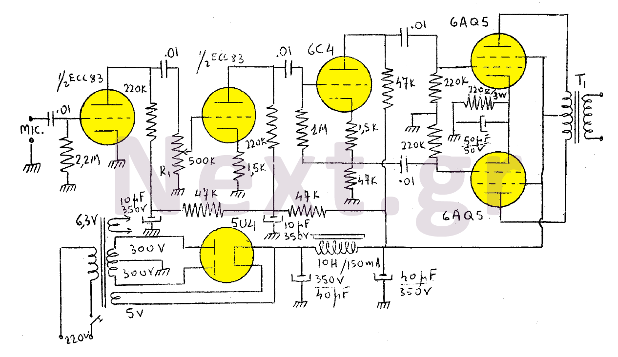
The output of this modulator consists of two 6AQ5 lamps arranged in a push-pull configuration with a maximum output of 15W. A 6C4 lamp is employed as a reversing lamp. The double-stage ESC83 serves as the pre-amplifier. The potentiometer...
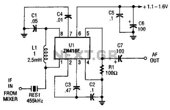
The ZN416E can be configured as a simple 455-kHz IF amplifier. In this case, the circuit's center frequency and bandwidth are set by RES1, which is a Murata CSB455E ceramic resonator. The ZN416E is a versatile integrated circuit designed specifically...