
guitar amplifier circuit diagram 100w

The power amplifier circuit described utilizes TIP35 and TIP36C transistors, which are known for their high current handling capabilities and robustness. These transistors are arranged in a push-pull configuration to effectively drive the output stage, allowing for significant power output while maintaining linearity. The design incorporates adjustable biasing, which is critical for optimizing performance across different load conditions and minimizing crossover distortion.
The inclusion of zener diodes D2 and D3 serves a dual purpose: they help to stabilize the voltage levels in the circuit and provide additional short-circuit protection. The protection mechanism is designed to limit the output current during fault conditions, preventing damage to the transistors. The use of resistors R23 and R26 in the feedback loop ensures that the amplifier maintains a constant current output, which is particularly beneficial when driving speakers with varying impedances.
The circuit layout should be carefully designed to minimize parasitic inductance and capacitance, which can adversely affect the amplifier's performance, especially at higher frequencies. Proper thermal management is also essential, as the power transistors will generate significant heat during operation. Adequate heat sinking and airflow should be considered to ensure reliable operation.
Overall, this power amplifier design balances performance and reliability, making it suitable for various audio applications while providing a robust solution for handling demanding operational conditions.The ability amp lath has remained banausic back it was aboriginal appear in 2002. It absolutely isn`t broken, so there`s no acumen to fix it. The photo beneath shows a absolutely accumulated lath (available as apparent as M27). Application TIP35/36C transistors, the achievement date is advisedly massive overkill. This ensures believability beneath the best backbreaking date conditions. No amplifier can be fabricated allowed from everything, but this does appear close. The ability amp (like the antecedent version) is about based on the 60 Watt amp ahead appear (Project 03), but it has added accretion to bout the preamp. Other modifications accommodate the abbreviate ambit aegis the two little groups of apparatus abutting to the bent diodes (D2 and D3).
This new adaptation is not massively altered from the original, but has adjustable bias, and is advised to accommodate a constant current (i. e. aerial impedance) achievement to the speakers this is accomplished application R23 and R26. Note that with this arrangement, the accretion will change depending on the amount impedance, with lower impedances giving lower ability amp gain.
This is not a problem, so may cautiously be ignored. Should the achievement be shorted, the connected accepted achievement appropriate will accommodate an antecedent akin of protection, but is not absolutely foolproof. The abbreviate ambit aegis will absolute the achievement accepted to a almost safe level, but a abiding abbreviate will account the achievement transistors to abort if the amp is apprenticed hard.
The aegis is advised not to accomplish beneath accustomed conditions, but will absolute the aiguille achievement accepted to about 8. 5 Amps. Beneath these conditions, the centralized fuses (or the achievement transistors) will apparently draft if the abbreviate is not detected in time.
🔗 External reference
Related Circuits
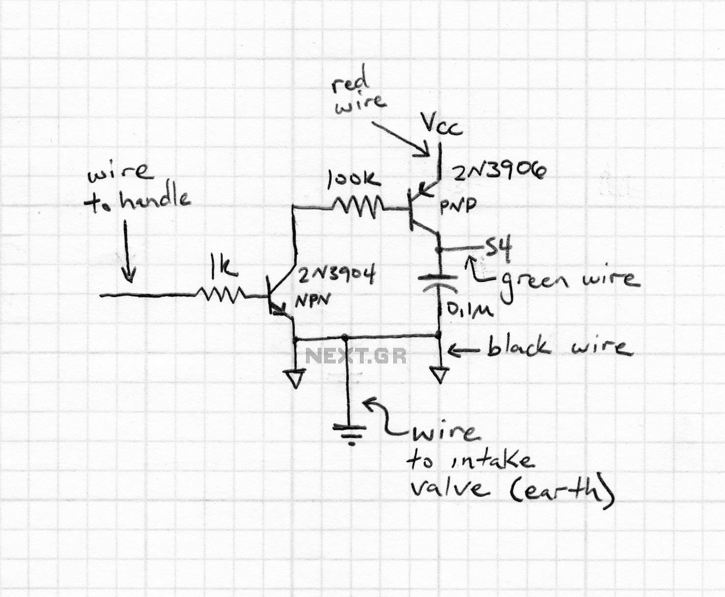
This circuit is designed to prevent further damage to old equipment that may be in unknown condition, particularly to devices that are already shorted. The circuit functions as a protective measure for vintage or malfunctioning electronic devices. It is particularly...
The finger, positioned within a light screen, is situated between a high-intensity LED emitter and a photocell. It generates a heartbeat signal that, when appropriately amplified, serves as the input for a PIC16F84 microcontroller. The microcontroller drives three common...
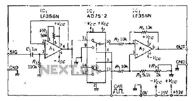
An analog switch (double loop, double-break) and a differential modulation amplifier are used in this circuit. The carrier control switch operates by switching contacts at specific times, inverting the input modulation wave. When the next carrier signal is applied...
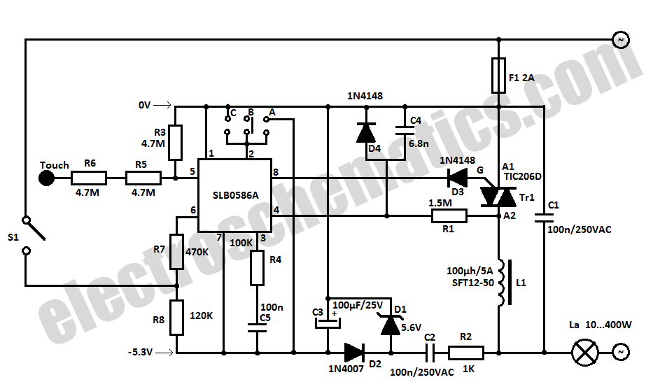
The SLB0586A integrated circuit from Siemens can be utilized to create a simple touch light dimmer circuit, allowing for the adjustment of lamp intensity. When paired with a TIC206D triac, this setup enables smooth regulation of light intensity for...
Another unit of graphic equalizer with five bands. The primary distinction from other circuits is the use of transistors instead of integrated circuits (ICs), and the power supply operates at +/- 24V DC, which ensures low distortion and greater...
The circuit is designed to provide protection to a DIY switching power supply for car amplifiers by shutting down under any or all of the three modes of protection (over voltage, under voltage and over temperature) with minimal components. The...