
Photo Alarm ElectronicCircuit With 555 Timer IC

The Photo Alarm Electronic Circuit utilizes a 555 Timer IC configured in monostable mode to create an alarm system that activates in response to changes in light levels. The circuit primarily consists of an LDR, which serves as the light sensor, and a resistor that forms a voltage divider with the LDR. The output from this voltage divider is fed into the trigger pin of the 555 Timer.
When ambient light levels drop below a certain threshold, the resistance of the LDR increases, causing the voltage at the trigger pin to fall below 1/3 of the supply voltage. This triggers the 555 Timer, activating the output pin, which can drive a relay or an alarm system. The duration for which the alarm remains active is determined by the timing components (resistors and capacitors) connected to the 555 Timer, allowing for customization of the alarm duration.
To ensure proper operation, it is crucial to select an appropriate LDR and timing components based on the specific application requirements. The circuit can be powered using a standard DC power supply, and additional features such as a reset button or adjustable sensitivity can be incorporated to enhance functionality. This design is suitable for various applications, including security systems, automated lighting, and other light-sensitive control systems.he following circuit shows a Photo Alarm Electronic Circuit. This circuit based on the 555 Timer IC. Features: LDR ( photoresistive cell), .. 🔗 External reference
Related Circuits
Figure 15-22 illustrates a doorbell system that consists of a monostable timing circuit, a password switch, a NAND gate circuit, and a sound output circuit. The operation of the circuit is designed such that when the password switch is...
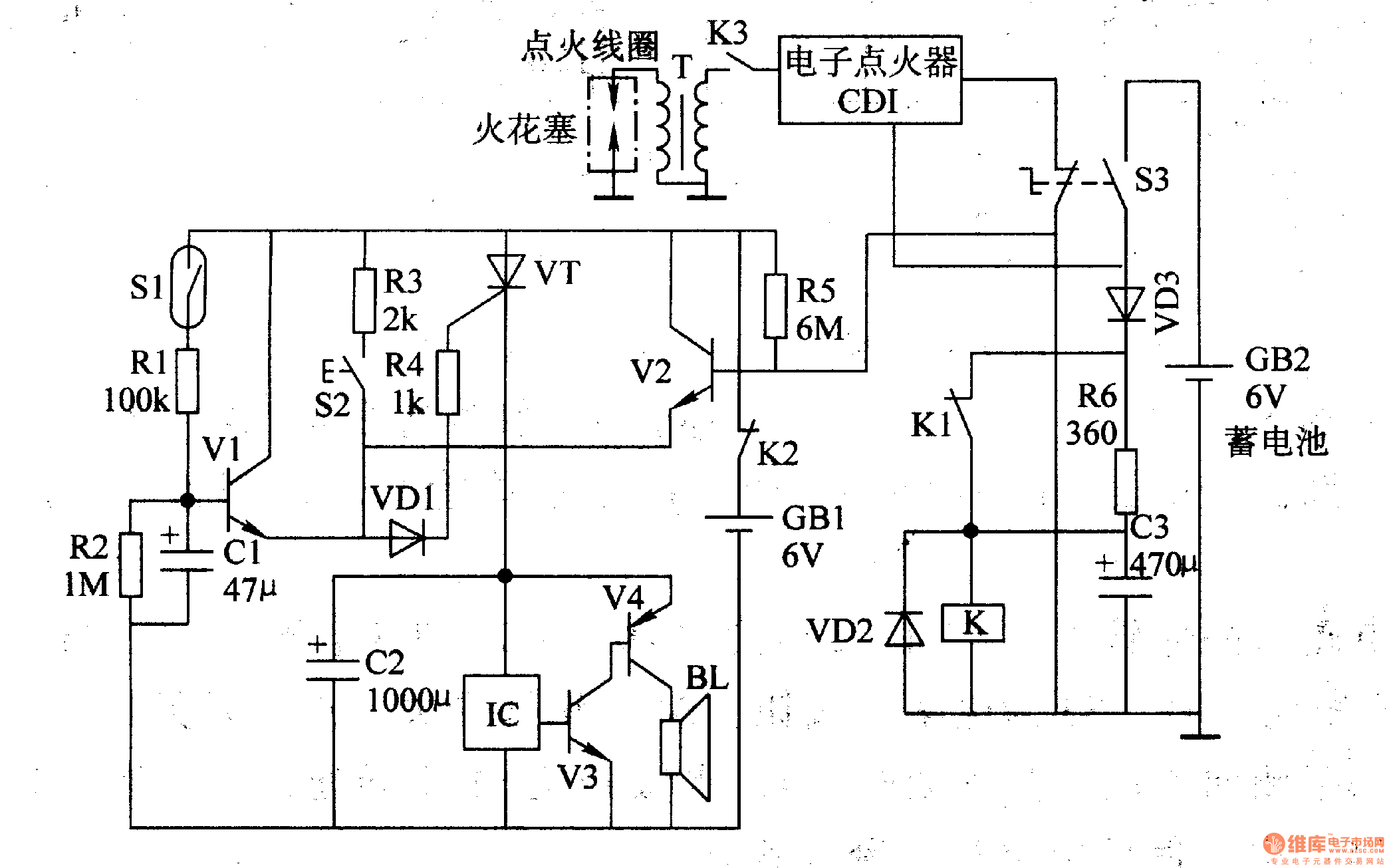
The multi-function motorcycle anti-theft alarm discussed in this article is suitable for anti-theft applications for all two-wheel motorcycles. The motorcycle anti-theft alarm circuit consists of a mobile delay alarm circuit, an ignition switch ground wire break alarm circuit, and...
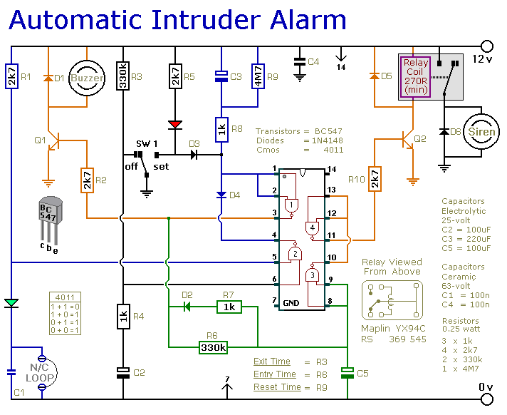
This is a simple single-zone burglar alarm circuit. Its features include automatic Exit and Entry delays and a timed Bell/Siren Cut-Off. It is designed to be used with the usual types of normally-closed input devices such as magnetic reed...
When the phototransistor is struck by IR light it conducts and the voltage between the 1Mohm resistor (arbitrary) and the phototransistor drops from VCC to lower values. When the voltage drops lower than VCC/3 the 555 is triggered and...
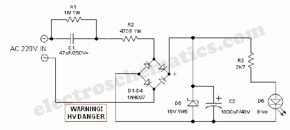
This circuit project automatically activates a night lamp when the bedroom light is turned off. The lamp stays illuminated until the light sensor detects daylight. The circuit operates using a light-dependent resistor (LDR) as the primary sensor to detect ambient...
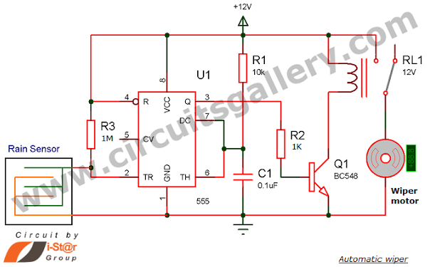
Have you seen Audi, Lexus, or Ford rain-sensing wipers and wondered how they operate in these vehicles? They are controlled by sensors located at the center of the windscreen, which detect raindrops and activate the wiper motor. The functioning...