
Amplitude Modulator with OTA

This circuit is designed for high-efficiency amplitude modulation, capable of achieving a modulation depth of 99%. The operational frequency range extends up to 200 kHz, making it suitable for various applications in communication systems. The circuit typically comprises several key components, including transistors for amplification, resistors for biasing, and capacitors for filtering and coupling signals.
The modulation process begins with an input signal, which is fed into the circuit. The transistors used in the design function as amplifiers, boosting the input signal's amplitude while maintaining the fidelity of the modulation. The circuit configuration may include feedback mechanisms to stabilize the gain and improve linearity, ensuring that the output signal closely follows the input signal's variations.
Furthermore, the circuit may incorporate a low-pass filter to eliminate unwanted high-frequency components that could affect the quality of the modulation. This filter is essential in maintaining the integrity of the modulated signal and preventing distortion in the output.
To achieve the desired modulation depth, careful selection of component values is crucial. Resistors and capacitors must be chosen to match the specific frequency response required for optimal performance. Additionally, the power supply must provide sufficient voltage and current to support the amplification stages without introducing noise or fluctuations in the output.
Overall, this circuit represents a robust solution for achieving high levels of modulation at significant frequencies, making it applicable in various electronic communication devices and systems.Circuit described in the schematic diagram below can achieve 99% modulation easily with maximum frequency of 200kHz. The amplification of this circuit can be.. 🔗 External reference
Related Circuits
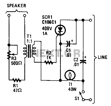
The lights appear to synchronize with the music. Line-voltage lamps rated between 40 to 100 watts function effectively. The current for the lamp is controlled by a silicon-controlled rectifier (SCR). When low-level audio signals are present across transformer T1,...
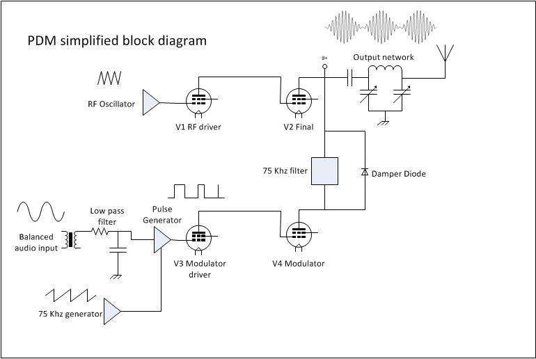
Amplitude Modulation (AM) is the first type of modulation that impressed audio onto a radio frequency (RF) carrier. Before AM, information was transmitted using on/off keying of a continuous wave transmitter, typically through Morse code or similar methods. 1....
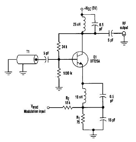
This varactorless high-frequency modulator electronic project must be powered by a simple DC 3-volt power source, such as a 3-volt battery. Traditionally, high-frequency oscillators are frequency-modulated using a varactor. However, varactors typically require a significant voltage change to achieve...
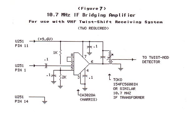
The material in this section demonstrates the construction of the Twist-Shift system for VHF utilizing commonly available surplus land mobile VHF transceivers that have been modified to operate on the 2-meter ham band. The radios employed in this project...

Here is a design circuit for a frequency modulator that is equipped with a tuning circuit. In this circuit, a pair of 1N4007 diodes is utilized as varactor diodes. The choice of 1N4007 diodes is not due to their...
The FSK demodulator is an electronic device that converts the FSK signal into a serial digital signal. FSK modulation is utilized to transmit digital serial data. The FSK (Frequency Shift Keying) demodulator serves a critical function in digital communication systems...