
Varactorless high frequency modulator circuit design electronic project

The varactorless high-frequency modulator circuit is designed to operate efficiently at low voltage levels, making it suitable for battery-powered applications. The use of base-charging capacitance modulation allows for effective frequency modulation without the complexity and limitations associated with varactor diodes. In this configuration, transistor Q1 serves as the active element, where its collector current is modulated by an external voltage signal (Vmod) applied through resistor R2. This modulation alters the effective capacitance at the base of Q1, which in turn influences the oscillation frequency of the circuit.
The transmission line T1, being a quarter-wave design, plays a crucial role in determining the resonant frequency of the oscillator. Its characteristics, including low-loss and high-quality materials, ensure that the oscillations are stable and sustained. The interaction between the negative resistance seen at the base of Q1 and the transmission line is essential for maintaining continuous oscillation. The circuit's design must ensure that the terminal impedances are correctly matched to optimize performance and achieve the desired frequency response.
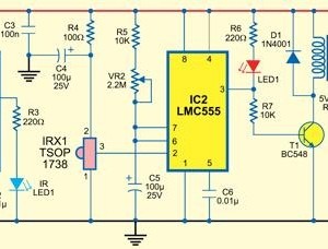
Overall, this varactorless high-frequency modulator represents an innovative approach to frequency modulation, leveraging base-charging capacitance modulation to overcome the limitations of traditional varactor-based designs. The simplicity of the power requirements, along with the efficiency of the circuit, makes it a valuable solution for various applications in the field of electronics.This varactorless high frequency modulator electronic project, must be powered from a simple DC 3 volt power source ( you can use a 3 volt battery). Traditionally, high-frequency oscillators are frequency-modulated by using a varactor. However, varactors usually require a large voltage change to achieve a reasonable capacitance change ; a problem
in many battery-powered systems. Such a problem can be overcome by employing base-charging capacitance modulation. Resistor R1 establishes Ql`s current, and R2 allows control of the collector bias current by Vmod. The transmission line (T1) in the negative resistance type oscillator determines the frequency of oscillation. T1 is a high-quality, low-loss, ceramic coaxial shorted quarter-wave transmission line. Under proper terminal impedances, a negative resistance is "seen" at Ql`s base. T1 reacts with this negative resistance to produce sustained oscillations, Frequency modulation is accomplished by changing Q1`s collector bias current and thus changing Ql`s base-charging capacitance.
This effect is "seen" at Ql`s base and causes a frequency shift in the resonators quarter-wave node. 🔗 External reference
Related Circuits
Observing and addressing the phase adjustment issues in electric transmission lines manually poses significant challenges, particularly in recording and normalizing three major problems. This design encompasses both software and hardware components, developed over an extended period. It is intended...
This simple circuit allows the use of an oscilloscope as a Time Domain Reflectometer (TDR). The operation involves sending a pulse down a cable and observing the resulting reflections. The circuit design for utilizing an oscilloscope as a Time Domain...
The Adjustable Timer circuit initiates timing upon activation. A green LED illuminates to indicate that timing is in progress. Once the designated time period elapses, the green LED turns off, the red LED activates, and an audible bleeper sounds....
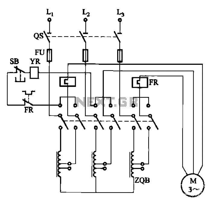
The circuit illustrated in Figure 3-47 involves a three-phase AC motor that is initially connected through a step-down autotransformer. To initiate operation, the power switch is closed, and the operating handle is pushed to the start position. Once the...
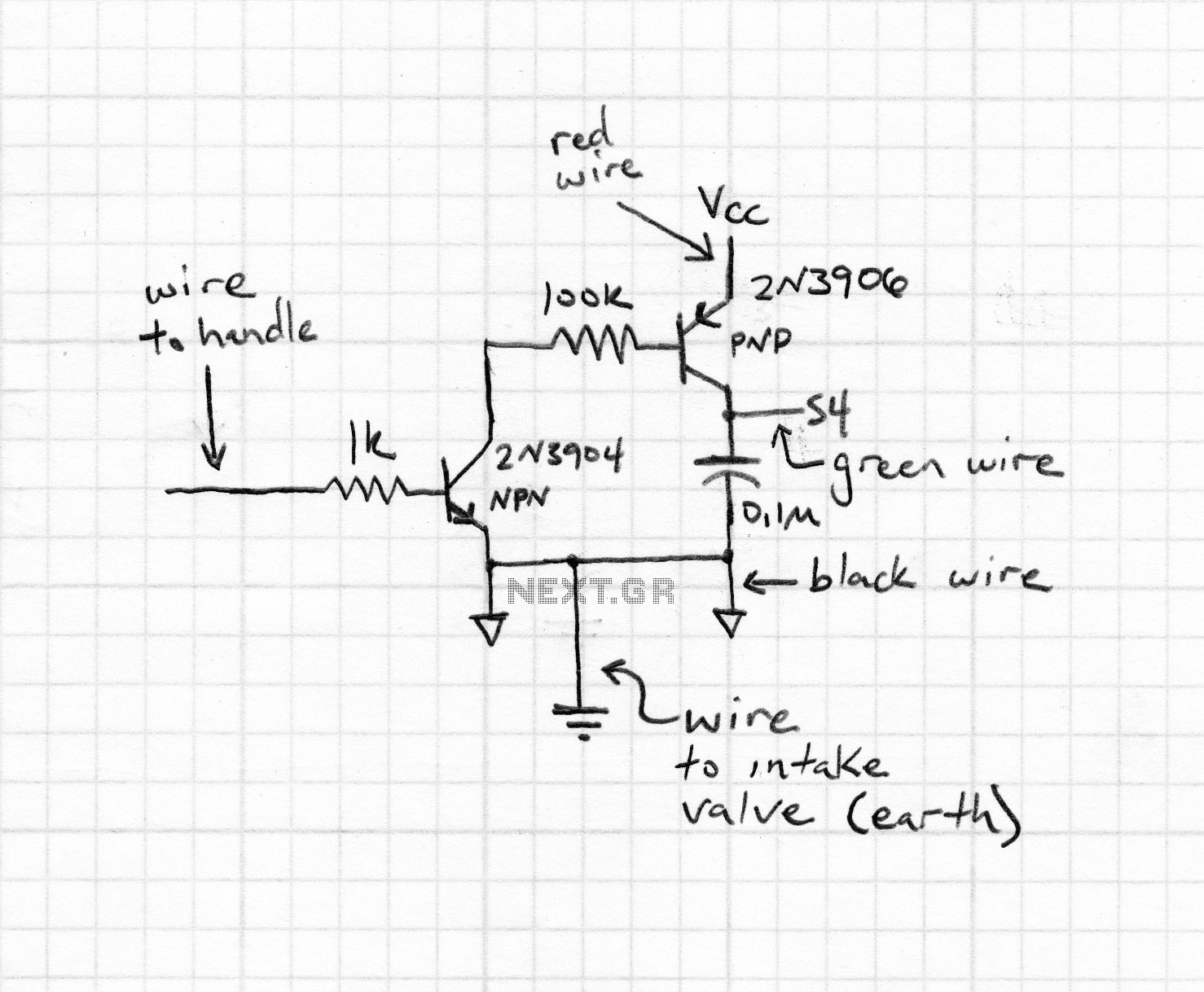
This type of infrared proximity circuit is commonly utilized as an electric switch where physical contact is undesirable for hygiene reasons. For instance, infrared proximity sensors are frequently found in public drinking fountains and washrooms. The straightforward circuit described...
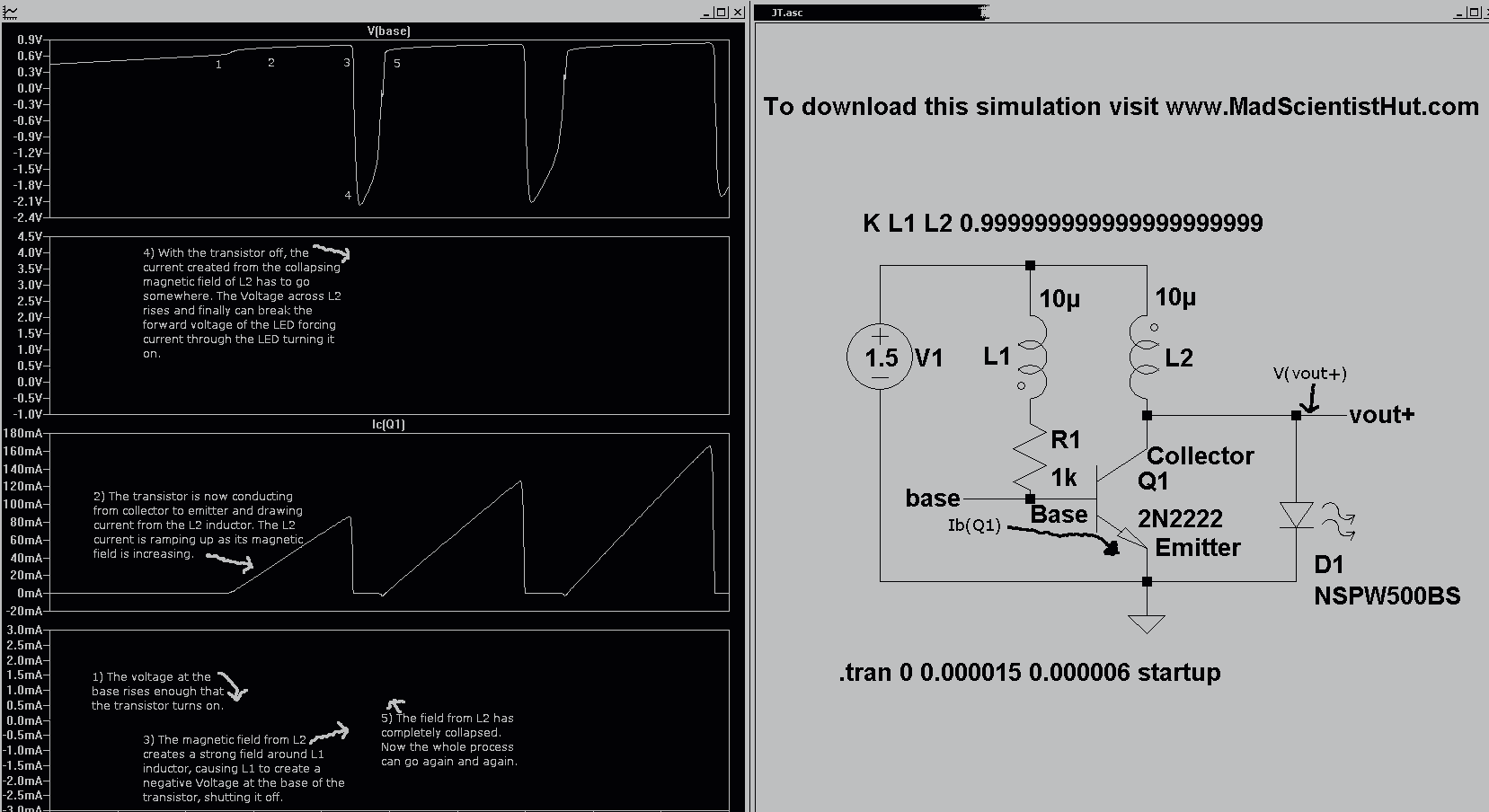
Introducing the Cree 1 Watt LED High Power Joule Thief Kit. Joule Thief Simulation II Graph and Schematic. The Cree 1 Watt LED High Power Joule Thief Kit is designed to demonstrate the principles of energy harvesting and efficient power...