
An Add-On Current Limiter For Your PSU circuit

The circuit operates on the principle of current limiting through the use of a power transistor, which is controlled by the voltage across a resistor (R2). The diodes in the circuit ensure that the base-emitter voltage of the transistor does not exceed safe levels, thereby protecting the transistor from damage due to excessive voltage. The choice of a 10-ohm resistor for R2 is a practical example, but the design allows for flexibility in selecting the resistor value to achieve desired current limits.
The LED indicator provides a visual cue for the user, making it easy to monitor the status of the output without needing additional measurement tools. This feature enhances the usability of the circuit, especially in experimental setups where quick visual feedback is beneficial.
The alarm function adds an important layer of safety for unattended operations, alerting the user to potential issues that may arise during testing. The inclusion of the buzzer circuit ensures that any significant drop in output voltage will trigger an audible warning, prompting immediate attention to the setup.
The heatsink design is crucial for thermal management, particularly when higher currents are involved. The specified dimensions of the aluminum strip are suitable for moderate power dissipation, but careful consideration should be given to the thermal requirements based on the maximum current the circuit is expected to handle. In high-current applications, a larger or more efficient heatsink may be necessary to prevent overheating and ensure reliable operation.
Overall, this circuit provides a practical solution for current limiting in various electronic applications, combining essential features with the flexibility to adapt to specific user needs.This circuit allows you to set a limit on the maximum output current available from your PSU. It`s very useful when you power-up a project for the first time - or carry out a soak-test. By setting an upper limit on the current available from your PSU - you can protect both your power supply - and any device connected to it. It offers a simple and cheap alternative to the Current Limiting Power Supply The basic circuit is shown in the first schematic. The two diodes fix the maximum possible voltage - on the base of the Power Transistor - at about 1v4.
This means that the maximum possible voltage across R2 is fixed at about 0v7. If R2 is 10 ohms - then the maximum possible emitter current is (0v7 G· 10) about 70mA. Since the collector current is always more or less equal to the emitter current - you cannot draw more than 70mA from the output terminals. If you try to do so - the output voltage will fall. I used a BD131 because that was what I had available. However, any NPN Power Transistor with a similar - or better - spec should work fine. I had no special reason for choosing a 70mA maximum. If you want to set a different current limit - change the value of R2. The formula is in the diagram. Always remember that if you increase the current - you`ll also increase the watts. The second schematic has a couple of added features. If you don`t want to use a voltmeter on the output - use an LED instead. If the output voltage falls - the LED will dim or extinguish completely. This is enough to let you know that the load on the output is excessive. Where the Current Limiter is to be left unattended for any length of time - say during a soak-test - the Buzzer is useful.
Should a problem develop - and the output voltage fall by 2-volts or more - the circuit will sound the alarm. The layout provided is for the second schematic - but it`s flexible. If you don`t want the LED feature - just leave out the LED and R3. If you don`t want the alarm feature - leave out D3, D4, D5, R4, R5 & Q2. The heatsink is a folded strip of aluminium about 2mm thick, 6cm long and 3cm tall. If you increase significantly the maximum current available from the limiter circuit - you`ll probably need to increase the size of the heatsink as well.
🔗 External reference
Related Circuits
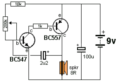
The ticking bomb sound generator circuit diagram operates by charging a 2.2 µF capacitor. When the voltage at the base of the NPN transistor reaches 0.65 V, it activates the transistor, which in turn activates the BC557 transistor, increasing...

The circuit utilizes a 555 timer IC to create a lighting group delay effect, as illustrated in Figure 2-46. It consists of the 555 IC along with a resistor and capacitor configuration that establishes the delay. The circuit remains...
So you’ve read about my Computerized Room or have seen those nifty home automation products advertised in the back of electronics magazines? Or perhaps someone you know has done something similar. At any rate, you have decided to try...
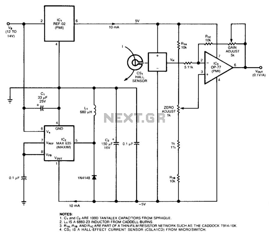
The circuit employs a Hall-effect sensor, which consists of an integrated circuit (IC) situated within a small gap of a flux-collector toroid, to measure direct current (DC) ranging from 1 to 40 A. The current-carrying wire is wrapped through...
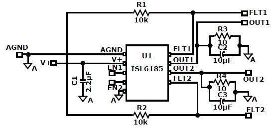
The ISL6185 USB power controller family can be utilized to design a straightforward USB power supply electronic project that offers fully independent overcurrent (OC) fault protection for two or more USB ports. This product family includes sixteen distinct functional...
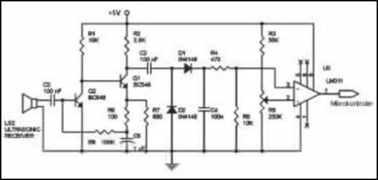
Ultrasonic receivers detect an ultrasonic signal emitted by an ultrasonic transmitter at a specific frequency. The received signal is filtered using a band-pass filter circuit that allows only the predetermined frequency range to pass. The output signal is then...