
An Anemometer Circuit

The circuit board in question is designed to handle a specific application, likely related to measuring or controlling wind flow, as inferred from the mention of wind flow accuracy. The primary function of the board is to ensure stable operation, which is critical for accurate readings and consistent performance in such applications.
At the heart of the circuit board is a 5 Volt voltage regulator, which is essential for providing a stable power supply. This regulator takes a higher input voltage and outputs a constant 5V, which is necessary for the reliable operation of various electronic components on the board. The choice of a 5 Volt regulator indicates that the circuit likely utilizes common components such as microcontrollers, sensors, or other integrated circuits that require this voltage level.
The design may include additional features such as bypass capacitors connected to the output of the voltage regulator to filter out noise and provide transient response improvements. This ensures that the voltage supplied to sensitive components remains stable even during load changes.
The circuit may also incorporate input and output terminals for easy connection to external devices or sensors. If wind flow measurement is the primary function, it is probable that the board interfaces with a flow sensor, which could be based on various technologies such as anemometers or pitot tubes, depending on the required measurement accuracy and application.
Furthermore, the layout of the circuit board should be optimized for minimal interference and maximum signal integrity. This might involve careful placement of components, routing of traces, and possibly the inclusion of ground planes. Such considerations are vital for applications where precision is paramount.
In summary, the circuit board is a carefully designed assembly intended to provide stable power and facilitate accurate measurements, particularly in the context of wind flow, while ensuring reliability and performance through the use of a 5 Volt regulator and thoughtful design principles.I designed up this circuit board because of a request from a visitor to my website. I also assemble the circuit board to Varify the board was correct. It does work, VERY NICELY, but I have no way to varify the accuracy of wind flow that is stated by the author. Since the Circuit Requires a Stable Supply, I have added a 5 Volt Regulator to the Circuit Board. 🔗 External reference
Related Circuits
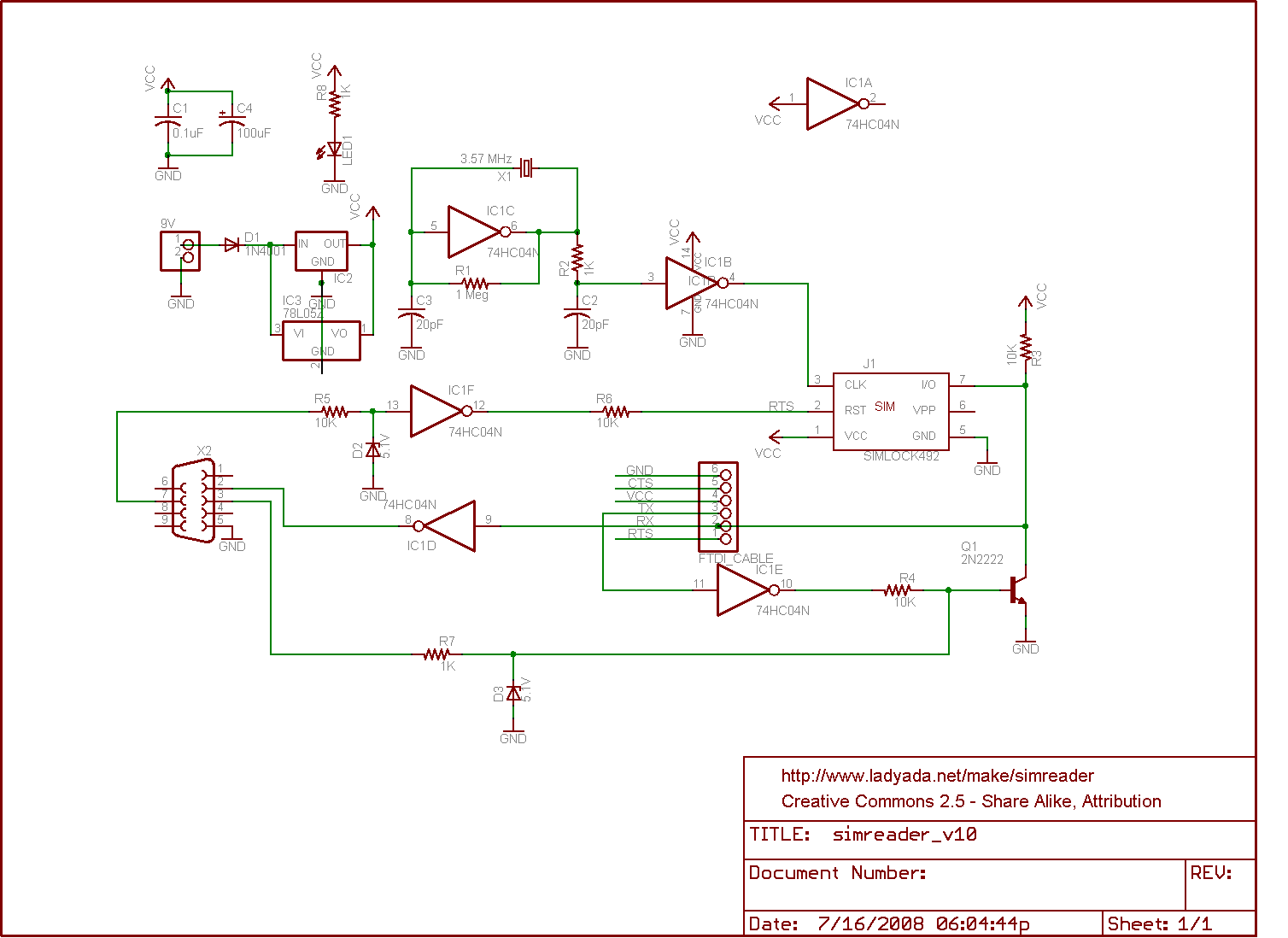
The circuit for a SIM card reader is presented here. It utilizes a CMOS hex inverter along with other basic components. Not only does it function effectively, but it is also capable of communicating with a PC through a...
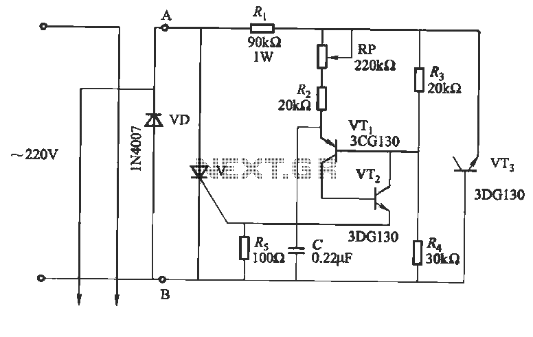
This circuit utilizes an "and other potential triggers" circuit. The term equipotential trigger refers to a crystal bidirectional thyristor trigger, which can be activated by either a positive or negative trigger. In this setup, the control electrode G and...
This circuit creates a buzz coil using a standard automotive ignition coil. A 556 dual timer is employed to establish the frequency and duty cycle of the coil current. One timer functions as an oscillator to generate the 200...

The tremolo circuit of the S950 is unique. The oscillator is a standard design, using half of a 12AX7. In the schematic above, the speed control is located at the lower right, the intensity control at the upper left,...
The diagram illustrates a human infrared remote sensing lamp circuit. It utilizes the trace infrared heat emitted by humans to control the lamp's operation, allowing it to turn on or off remotely. This human infrared remote sensing lamp features...
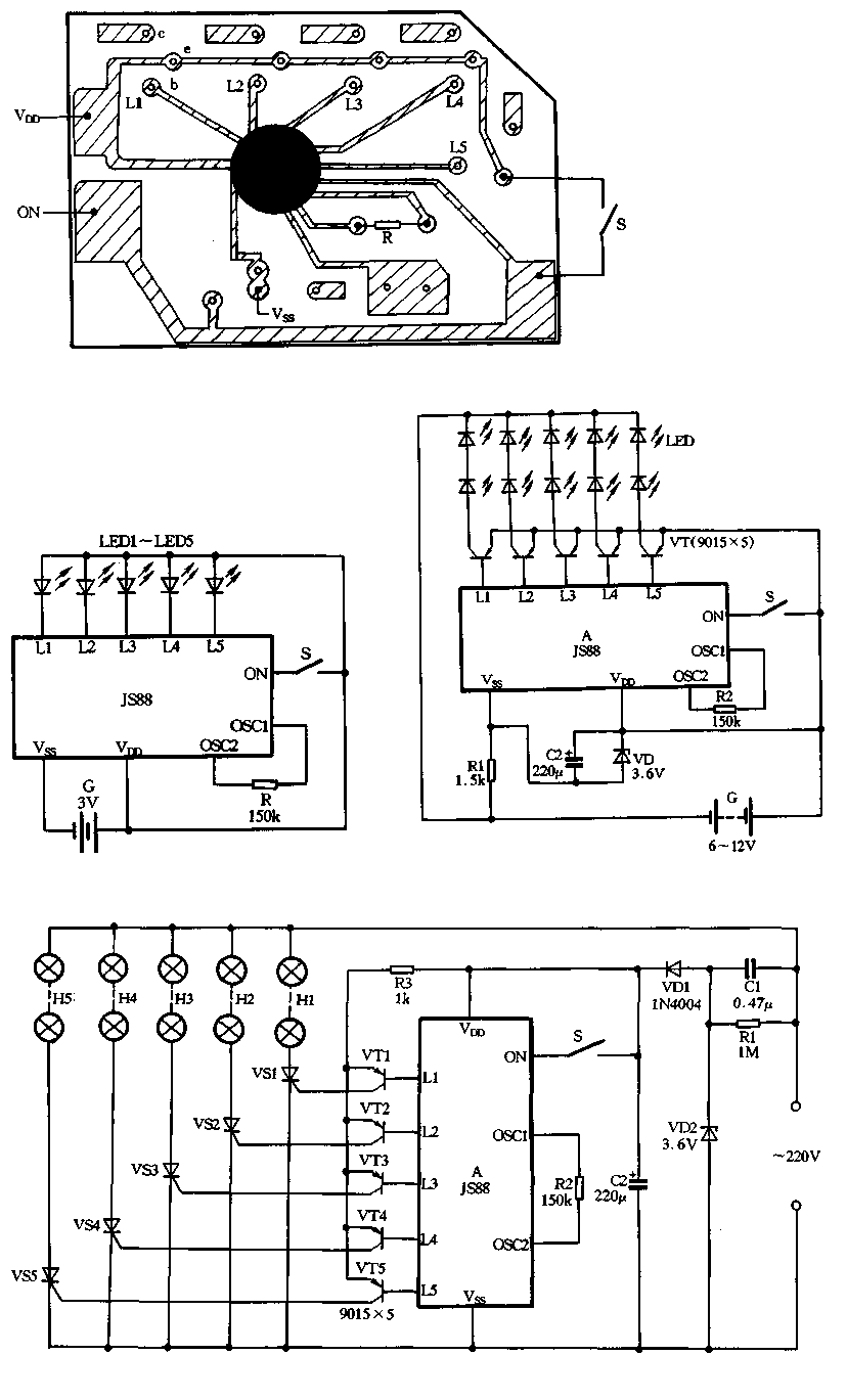
Figure 2-39 illustrates a typical application circuit for the JS88 manifold, which includes an oscillation resistor (R) that allows for fine-tuning of the water flicker frequency. When switch (S) is closed, components L1 to L5 sequentially output low signals...