
tremolo circuit

The tremolo circuit in the S950 employs a half of a 12AX7 vacuum tube as the core component for the oscillator, which is a common design in audio effects circuits. The oscillator generates a modulating signal that varies the amplitude of the audio signal, creating a tremolo effect.
The speed control, positioned at the lower right of the schematic, allows the user to adjust the rate at which the modulation occurs. This control typically varies the frequency of the oscillator, thereby changing how quickly the tremolo effect pulses. The intensity control, found at the upper left, adjusts the depth of the modulation, influencing the extent to which the audio signal is affected by the tremolo. A higher intensity setting results in a more pronounced effect, while a lower setting produces a subtler modulation.
The output of the oscillator signal, which exits the circuit at the upper right of the schematic, is then typically routed to a mixing stage where it combines with the original audio signal. This mixing stage may involve additional components such as resistors and capacitors to shape the final output. The unique aspect of this circuit may lie in the specific configuration and interaction of these components, which can create a distinctive tremolo sound that sets the S950 apart from other devices.
In summary, the tremolo circuit of the S950 is characterized by its use of a 12AX7 tube oscillator, with clearly defined controls for speed and intensity, culminating in a unique modulation output that enhances the audio experience. The tremolo circuit of the S950 is unique. The oscillator is a standard design, using half of a 12AX7: In the schematic above, the speed control is at lower right, the intensity control upper left, and the oscillator signal leaves this picture at the upper right. What happens next is a little weird: The schematic above.. 🔗 External reference
Related Circuits
Normally the base of a cordless phone has an adaptor and the handset has Ni-Cd cells for its operation. The base unit becomes inoperative in case of power failure. In such conditions, it is better to provide a backup...
Application circuit using three stereo digital potentiometers to control volume, balance, and fader in a four-speaker configuration with a push-button interface. The application circuit utilizes three stereo digital potentiometers, which are essential components for managing audio levels in a multi-speaker...
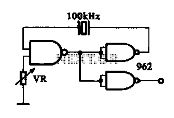
A DTL integrated circuit comprises a crystal oscillator, which is represented by the integrated circuits. The oscillation frequency ranges from 100 kHz to 1 MHz. Additionally, it includes a gate circuit that supplies a signal for the DTL oscillator...
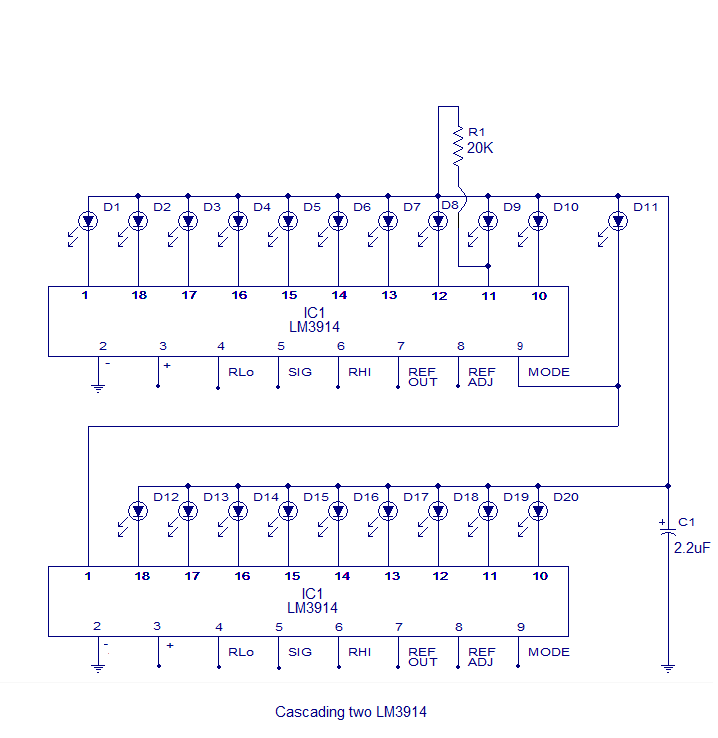
The core of this circuit is the LM3914 from National Semiconductor. The LM3914 is capable of sensing voltage levels and can drive a display of 10 LEDs in either dot mode or bar mode. The selection between bar mode...

Q1 functions as a Colpitts crystal oscillator. If the crystal being tested is operational, the RF signal is rectified by diodes D1 and D2, which activates Q2 and illuminates indicator LED2. Additionally, LED1 serves as a power indicator. The circuit...
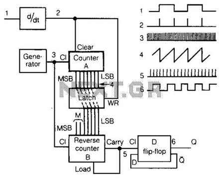
An input rectangular signal is differentiated to produce short impulses from its edges. These impulses transfer the content of counter A to a latch that clears the counter after a very brief period. Counter A counts impulses at a...