
An Introduction To Verilog Circuit

The schematic integrates various components that enhance the functionality of the CPLD development board. The inclusion of eight DIP switches offers a straightforward method for user input, facilitating the selection of different operational modes or configurations. Each switch connects to designated I/O pins on the CPLD, enabling the programming of specific actions based on the switch positions.
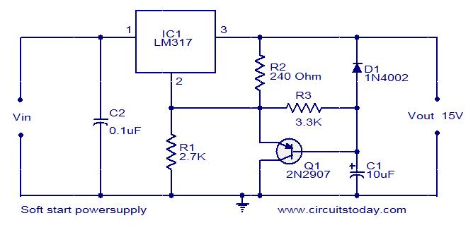
The power supply section is designed to ensure reliable operation of the circuit. The 9V battery feeds into the LM7805 voltage regulator, which outputs a steady 5V DC. The addition of capacitors at the output and ground of the LM7805 serves to filter any voltage fluctuations, thereby maintaining stable power to the CPLD and associated components.
The programming interface, utilizing a shrouded 10-pin JTAG header, is a critical component for uploading configurations and programs to the CPLD. Careful attention to wiring in this section is essential, as incorrect connections could lead to permanent damage to the programming hardware.
The 7-segment LED display is a key output device in this schematic, providing a visual representation of the data processed by the CPLD. The connection of the display to pins 61-70 allows for direct control over each segment, making it possible to display numerical values based on the input from the DIP switches. The current limiting resistors are crucial for protecting the LEDs from excessive current, thus ensuring longevity and reliable operation.
Overall, the schematic represents a well-thought-out design that incorporates essential features for both input and output, making it suitable for various applications in digital logic design and prototyping.The schematic is very similar to the one seen in the CPLD Development Board Tutorial because it`s basically the same board with a tiny addition. The new part of the schematic is in the lower right corner. 8 (DIP) Switches, a resistor array & some additional wiring. Notice the pins that the switches are connected to on the CPLD, these will be impor tant later on when you choose I/O pins in the program. The power circuit is a 9v Battery hooked up to the LM7805 with several capacitors attached to output & ground of the LM7805 to keep a steady 5v DC. The programming circuit uses a "shrouded header" with 10 pins. This is a standard JTAG header. We will use this to program the CPLD with the ByteBlaster MV cable. Double check the wiring on this part of the board otherwise you might fry your ByteBlaster cable! The 7 segment led display is wired up to 7 pins between 61-70 on the CPLD. These 7 pins control which leds are lit up inside the display. For our purposes in this project we`ll only make a simple program that lights them all up, nothing too fancy.
The 100 resistors that precede the display are just current limiting resistors. These allow the user to give input and ultimately decide what is to be displayed on the 7-Segment LED Display. Depending upon which bit is set, the corresponding number will be displayed on the display (1->1, 2->2, etc.
). 🔗 External reference
Related Circuits
This circuit provides automatic current limiting up to 8.4 A. Unlike current limiters that use only a resistor, this current limiting circuit does not drop the voltage significantly or keeps the voltage drop to a minimum until a specific...
The 7208 seven-stage decimal counter can be utilized as a frequency counter. It features latch and multiplexing functions, along with direct digital driving circuitry and display driving circuitry. The output frequency of the 7207 IC 6.5536 MHz crystal oscillator...
This post presents an interesting topic about switching power supply circuit diagrams for those who wish to learn more. A switching power supply is a type of power supply that uses a switching regulator to convert electrical power efficiently. Unlike...
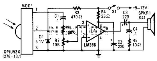
This circuit utilizes an infrared pulse-to-audio converter to assist in troubleshooting infrared remote controls, making it an effective tool for detecting infrared light sources. It employs a photo cell module (Radio Shack P/N 276-137) to detect IR radiation and...
This solar battery charger is a simple and cost-effective project suitable for hobbyists. While it has some limitations compared to other similar devices, it offers several advantages. The charger is designed for lead-acid batteries but can also charge any...
This schematic is directly sourced from the Altera ByteBlaster datasheet or manual, which provides comprehensive details regarding the connector's functionality and pin connections. It is advisable to review the datasheet available on their website or through a search engine...