
Ir Pulse To Audio Converter Circuit

The infrared pulse-to-audio converter circuit operates by converting the infrared signals emitted by remote controls into audible sound. The heart of the circuit is the photo cell module, which is sensitive to infrared light. When an infrared signal is detected, the module generates a corresponding electrical signal. This signal is then fed into audio IC U1, which processes it to produce an audible output.
The circuit typically consists of a few key components: the photo cell module (P/N 276-137), audio IC U1, resistors, capacitors, and a power supply. The photo cell module is connected to the input of the audio IC, and it typically requires a power supply of around 5V to operate efficiently. Resistors may be used to adjust the sensitivity of the photo cell and to limit the current flowing into the audio IC, ensuring that it operates within its safe limits.
Capacitors can be included to filter out noise and stabilize the power supply to the audio IC, providing a cleaner output signal. The output from the audio IC can be connected to a small speaker or an audio output jack, allowing the user to hear the converted infrared signals as audible sounds.
This circuit can be particularly useful for technicians and hobbyists who need to diagnose issues with remote controls or for educational purposes to demonstrate the principles of infrared communication and audio signal processing. By providing audible feedback when an infrared signal is detected, users can easily identify the operation of remote controls and analyze their functionality. If your ear is good, you can use this IR-pulse-to-audio converter to troubleshoot infrared remote-controls. It is also a good project for detecting infrared-light sources. A photo cell module (Radio Shack P/N 276-137) detects IR radiation and drives audio IC Ul. This circuit is useful for troubleshooting IR remote controls.
Related Circuits
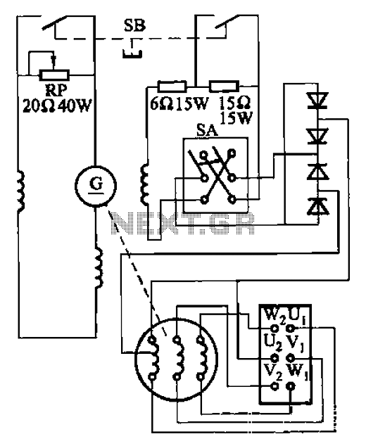
The AX3-300-2 DC arc welding machine circuit is part of the AX, AX1, AX3, and AR series of rotary DC arc welding machines. These machines share a similar structural design, featuring a three-integral unit configuration that combines an inverter...

This is a straightforward and easy-to-construct infrared (IR) receiver circuit. The circuit utilizes only a few components and is capable of receiving a 38 kHz carrier signal. The operation of this circuit is simple; whenever the IR LED detects...
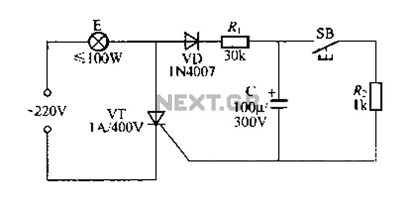
Figure 57 illustrates a simple delay lamp circuit that connects to lamp E using a two-wire connection. This design allows for the security bars to be installed directly, enabling replacement with a standard wall switch without altering the existing...
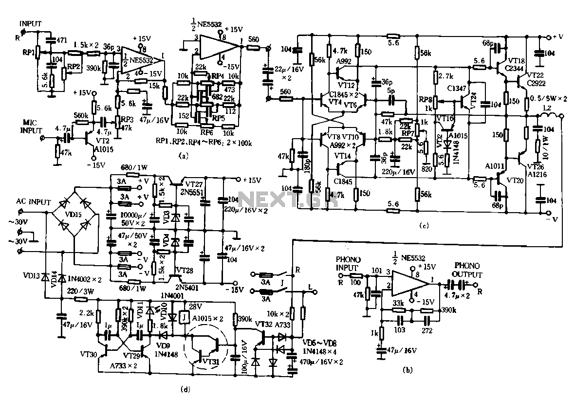
Only the R channel is shown, with the original reference PCB label. Figure (a) illustrates the front tone circuit, which consists of a common negative feedback operational amplifier in an RC circuit configuration. The microphone signal is amplified by...
There are many who built the Easy Programmer or C-52 Evaluation Board, asking for the RS232C level converter chip, DS275. Many have changed to MAX232 instead, because it is not available in their home. Here is another simple and...
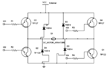
The diagram below illustrates an H-Bridge circuit featuring four inputs and an external power supply. The control application must enable the motor to operate in both forward and reverse directions. The H-Bridge is a crucial component in motor control applications,...