
Analog multiplexer

The adapter circuit is designed to facilitate the manipulation and display of both digital and analog signals effectively. The dual four-channel analog multiplexer serves as the core component, allowing for the selection of one of several input signals for further processing. This is particularly useful in applications requiring the comparison or analysis of multiple signal sources.
The upper half of the multiplexer selects the desired input channel, which is then routed to the output for display. This selection process is critical for ensuring that the correct signal is presented at any given time. Meanwhile, the lower half of the multiplexer generates a staircase waveform, which acts as a baseline offset for each channel. This offset is essential for maintaining the clarity of the displayed signals, as it prevents overlap and confusion between different input channels.
To enhance the performance of the staircase waveform, an emitter-follower buffer is employed. This configuration provides high input impedance and low output impedance, ensuring that the staircase signal does not load down the multiplexer output. The buffered staircase is then summed with the selected input signal, allowing for a composite output that accurately represents the desired waveform alongside the baseline offset.
Addressing the CMOS 4052 multiplexer is managed by a two-bit binary counter, which provides a straightforward method for selecting the input channels. This counter allows for easy cycling through the available channels, enabling dynamic switching between different signals without the need for complex control logic. The combination of these components results in a versatile and efficient adapter circuit suitable for a variety of electronic applications, including signal processing, data acquisition, and audio signal management.This adapter circuit, based on a dual four-channel analog multiplexer handles digital signals to at least 1 MHz, and analog signals at least through the audio range. The dual multiplexer's upper half selects one input for display. The lower half generates a staircase to offset the baselines of each channel, keeping them separate on the screen.
The emitter-follower buffers the staircase, which is then summed with the selected signal. A two-bit binary counter addresses the CMOS 4052 multiplexer.
Related Circuits
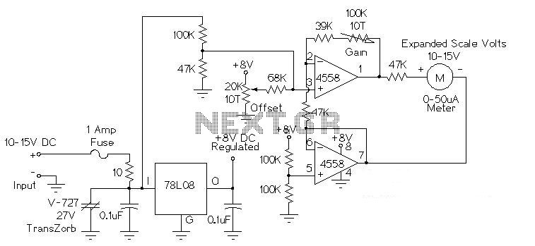
This circuit is used to measure the voltage on a 12V (nominal) lead acid rechargeable battery system. It was specifically designed for use in solar powered systems, but is general enough that it can be used for automotive or...
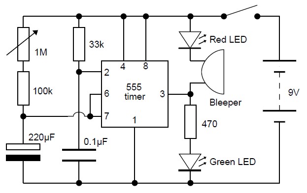
This adjustable analog timer circuit begins timing when it is activated. A green LED illuminates to indicate that the timing is in progress. Upon completion of the set time period, the green LED turns off, a red LED activates,...
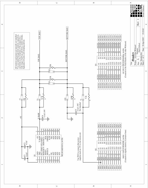
The I/O Filter Wildcard offers an efficient platform for prototyping analog circuits or for filtering, conditioning, or protecting the I/O lines of other Wildcards. It features twenty-four I/O lines that can be independently filtered or combined in customized configurations....
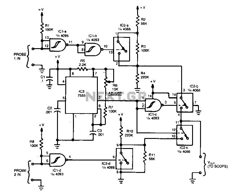
The operation of the unit revolves around three integrated circuits (ICs): a 4093 quad NAND Schmitt trigger, a 4066 quad analog switch, and a 7555 timer. When a high signal is applied to probe 1 input, it is inverted...
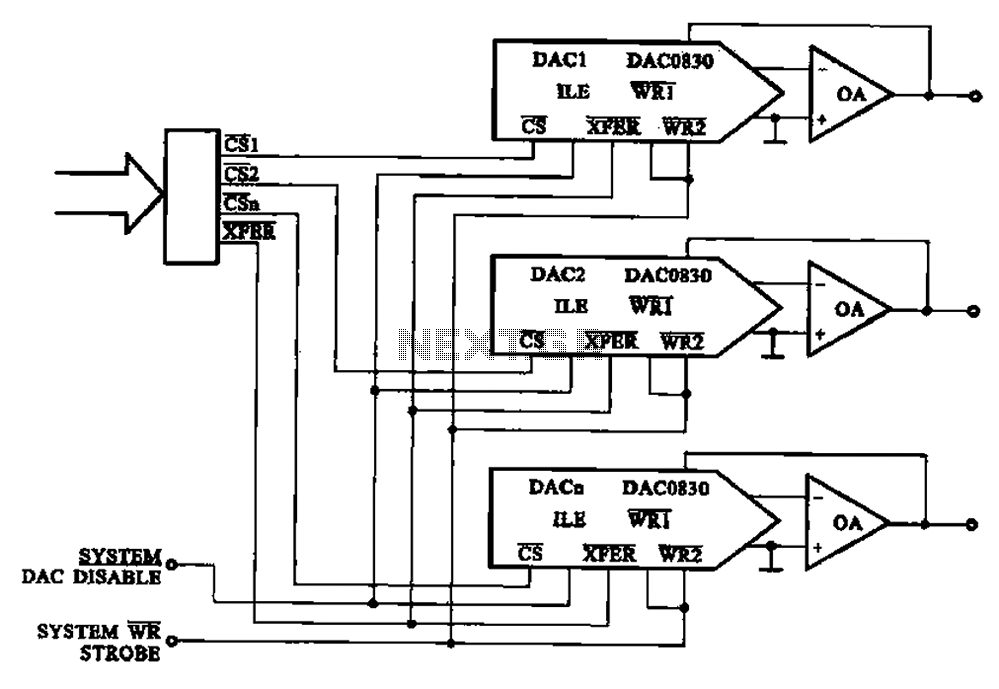
A multi-channel D/A converter circuit is presented, illustrating its fundamental structure. This circuit effectively converts encoded digital signals into multiplexed analog signal outputs. The multi-channel Digital-to-Analog (D/A) converter circuit is designed to facilitate the conversion of digital signals into corresponding...
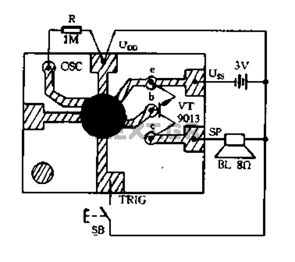
Constantly changing light and sound analog controller circuit 01 The described circuit functions as an analog controller designed to modulate light and sound outputs in a dynamic manner. This circuit typically integrates various electronic components, including resistors, capacitors, transistors, and...