
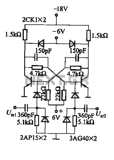
The basic structure of the DA conversion circuit multiplexer

The multi-channel Digital-to-Analog (D/A) converter circuit is designed to facilitate the conversion of digital signals into corresponding analog signals across multiple channels. The basic structure typically consists of several key components, including a digital input interface, a D/A conversion unit, and an output stage that generates the multiplexed analog signals.
At the core of the circuit is the D/A converter itself, which can be implemented using various technologies such as resistor ladder networks, current steering methods, or sigma-delta modulation techniques. Each channel of the D/A converter receives a digital input, which is often in binary form, and translates it into an analog voltage or current that reflects the digital value.
The digital input interface may include shift registers or latches to hold the incoming digital data, ensuring that it is stable during the conversion process. The output of the D/A converter is then routed to a multiplexing unit, which is responsible for selecting the appropriate channel output based on control signals. This allows multiple channels to share a single output line, thereby optimizing the use of resources and minimizing the required physical space for the circuit.
The output stage may include additional filtering components, such as low-pass filters, to smooth out the analog signals and reduce any high-frequency noise resulting from the digital conversion process. The overall performance of the multi-channel D/A converter circuit is crucial for applications requiring high fidelity in audio, video, or signal processing tasks, where accurate representation of the analog signal is essential.
In summary, the multi-channel D/A converter circuit is a vital component in modern electronic systems, enabling the effective transformation of digital data into usable analog signals across several channels, thereby enhancing the functionality and versatility of electronic devices.33. DA converter circuit ; Shows the basic structure of the multi-channel D/A converter circuit, it can be more consistent with the encoded signal is converted into a digital s ignal multiplexed analog signal output.
Related Circuits
To create a versatile and generic microcontroller board, the information provided thus far is sufficient. It covers the essential components needed to achieve this. The design of a microcontroller board requires careful consideration of various factors to ensure versatility and...
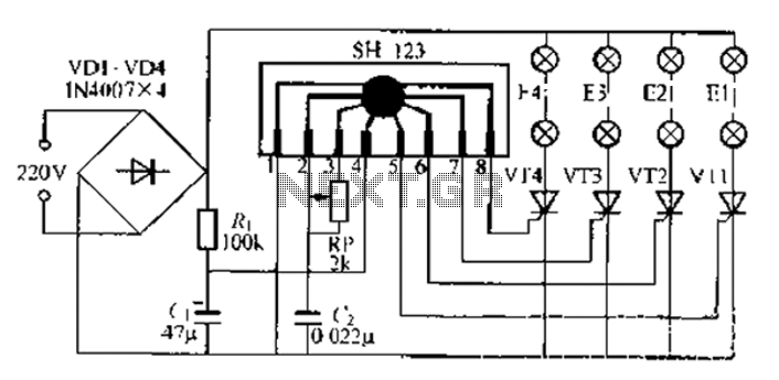
A water Happy Valley-type four flashing lights string controller, electric bollard is designed for use with a type J Ding Japanese lantern. The circuit employs a specific integrated circuit (IC) utilizing CMOS technology. It features a black soft cream...
A combination of shunts and multipliers, selected via a switch, can be utilized alongside a single basic meter to create a multirange instrument known as a multimeter. This device is capable of measuring voltage, current, and resistance. A multirange...
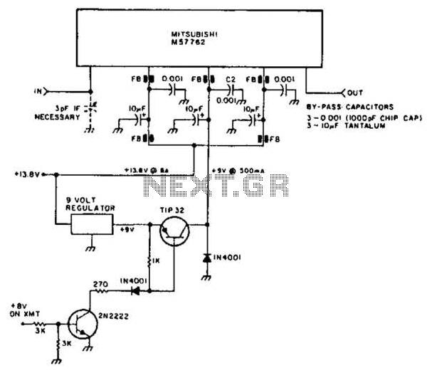
Using a Mitsubishi M57762 amplifier module, this amplifier delivers 20 W output at 1296 MHz. A single 12 V nominal power supply can be used. The Mitsubishi M57762 is a high-performance RF amplifier designed for applications requiring significant power output...
A flip-flop circuit with a memory function for pulse signals. It features two stable states: one where transistor VTi is off and VTZ is conducting, and another where VTi is conducting and VT2 is off. An external signal is...
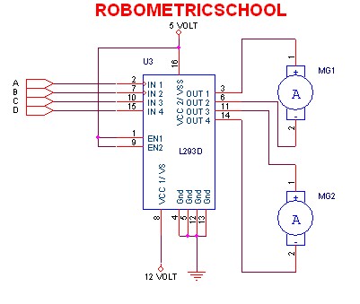
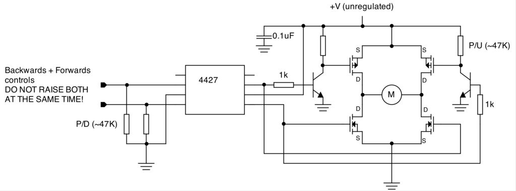
The electronic schematic of a DC motor driver using the L293D, as illustrated in Figure 2, enables the control of two DC motors continuously. It allows for one motor to rotate clockwise while the other rotates counterclockwise. Additionally, all...