
Analog to Digital Conversion and Communicating with a PC through the Serial Port

The system described involves the process of data collection through analog-to-digital conversion, enabling communication with a personal computer via a serial port interface. The microcontroller advanced kit serves as the central processing unit, facilitating the conversion of analog signals into digital data that can be transmitted to a PC for further processing and analysis.
The core of this system includes an analog sensor that captures real-world signals, such as temperature, light intensity, or pressure. The analog output from the sensor is fed into an analog-to-digital converter (ADC) integrated within the microcontroller. The ADC samples the analog signal at specified intervals, converting it into a digital representation. This digital data is then stored in the microcontroller's memory.
Communication with the PC is achieved using a serial communication protocol, which allows for efficient data transfer. The microcontroller is equipped with a Universal Asynchronous Receiver-Transmitter (UART) that manages the serial communication. Data is sent from the microcontroller to the PC in a sequential manner, typically using standard protocols such as RS-232 or USB, depending on the specific design of the microcontroller kit.
To implement this system, a schematic diagram is typically employed, illustrating the connections between the analog sensor, the microcontroller, the ADC, and the serial communication interface. Key components in the schematic may include:
1. **Analog Sensor**: The input device that generates an analog voltage corresponding to the physical parameter being measured.
2. **Microcontroller**: The main processing unit that executes the control algorithms, manages the ADC, and handles communication with the PC.
3. **Analog-to-Digital Converter (ADC)**: A component that converts the analog signal from the sensor into a digital format suitable for processing by the microcontroller.
4. **UART Interface**: The communication module that allows the microcontroller to send and receive data to and from the PC via the serial port.
Power supply considerations must also be addressed in the schematic, ensuring that all components operate within their specified voltage levels. Additionally, decoupling capacitors may be included to stabilize the power supply and filter out noise.
This system is particularly useful for applications in data logging, remote monitoring, and control systems, where real-time data acquisition and processing are essential. The combination of analog-to-digital conversion and serial communication provides a robust framework for developing various electronic applications.Data Collection - Analog to Digital Conversion and Communicating with a PC through the Serial Port Microcontroller Advanced Kit.. 🔗 External reference
Related Circuits
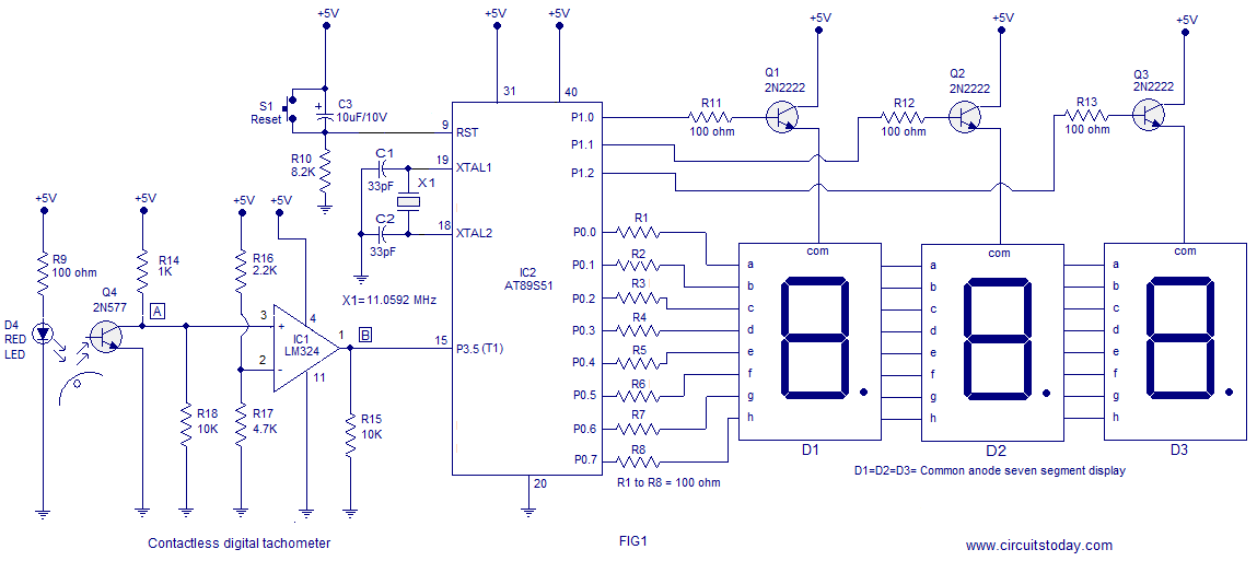
A three-digit contactless digital tachometer utilizing an 8051 microcontroller is presented for measuring the revolutions per second of rotating objects such as wheels, discs, or shafts. The tachometer can measure up to a maximum of 255 revolutions per second...
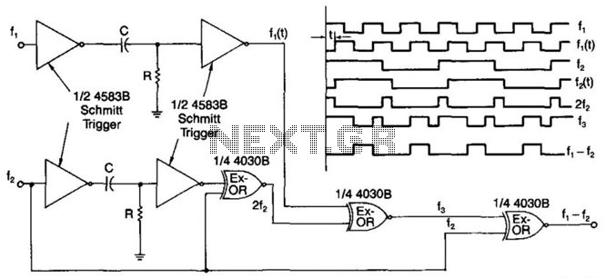
A simple digital mixer uses two dual-Schmitt triggers (4583B) and three exclusive-OR gates, incorporating an RC time-delay circuit to allow for easy adjustment of the output signal pulse width. The exclusive-OR gates can also function independently as a symmetrical...
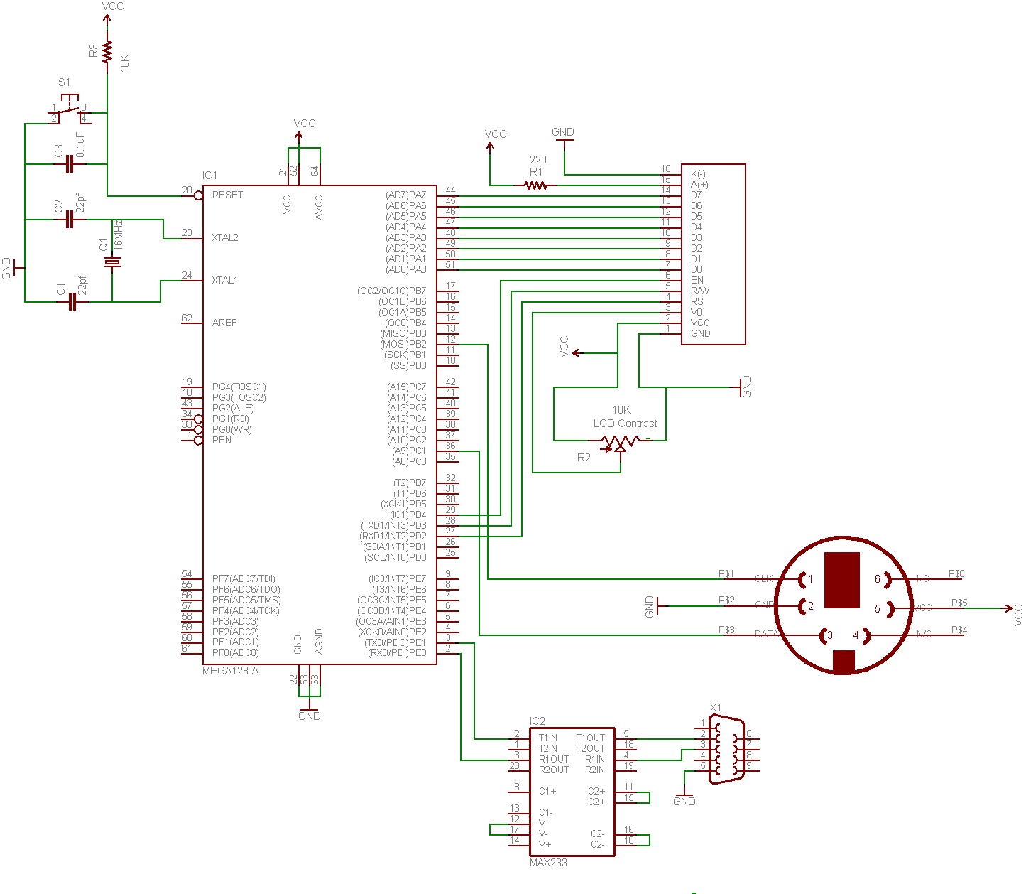
This guide demonstrates how to create a simple terminal using a keyboard, LCD screen, and an 8-bit microcontroller. A portable terminal can be useful for troubleshooting a headless server, building a minicomputer from a WRT, or learning how to...
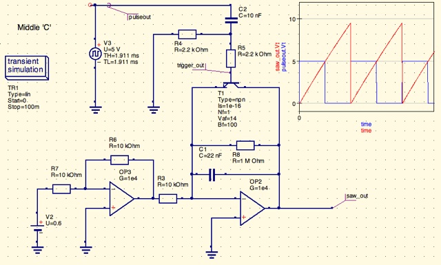
A design for a digitally controlled analog oscillator is being developed. The control voltage is generated by a microcontroller (Arduino) and is utilized through two operational amplifiers, along with a resistor and capacitor network that forms an integrator circuit....
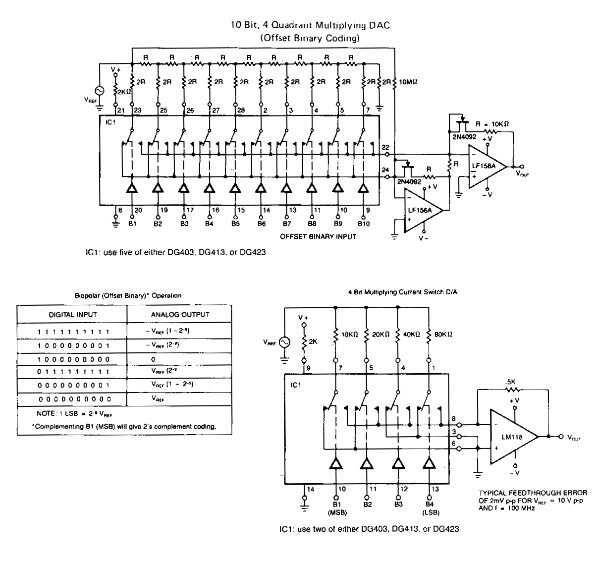
The following application circuits are designed to demonstrate several key concepts: A 2 kΩ resistor should be placed in series with the voltage source to limit supply current and mitigate negative ringing on the bit inputs. Temperature compensation for...
This circuit is designed to digitally adjust the volume of an analog audio signal. It employs a single AVR microcontroller to generate a pulse width modulated (PWM) signal for control. The innovation of the circuit lies in the utilization...