
Digital Mixer

The described digital mixer circuit utilizes two dual-Schmitt triggers (part number 4583B) to process input signals, enhancing signal integrity by providing hysteresis. This characteristic is particularly beneficial in noisy environments, where it helps to clean up the input signals. The inclusion of three exclusive-OR gates allows for versatile functionality, enabling both mixing and frequency doubling operations.
The RC time-delay circuit is a critical component, allowing for the adjustment of the output pulse width. The time delay, denoted as t, is determined by the resistor-capacitor (RC) combination and is expressed as t = RC ln(V+/Vt). Here, V+ is the upper threshold voltage and Vt is the lower threshold voltage of the Schmitt triggers. This relationship ensures that the timing of the signals f1 and f2 is synchronized, which is essential for the accurate subtraction of these signals.
It is important that the time delay applied to both signals f1 and f2 is less than half the period of f1 to maintain signal integrity and avoid distortion in the output. The condition that f1 must be greater than twice the value of f2 ensures that the circuit can effectively produce a meaningful output, which is the difference between the two input signals (f1 - f2). This output can be utilized in various applications, such as audio mixing or signal processing, where precise control over signal characteristics is required.
Overall, the design of this digital mixer circuit is efficient and adaptable, making it suitable for a range of electronic applications that require signal manipulation and processing. A simple digital mixer, based on two dual-Schmitt triggers (4583B) and three exclusive-OR gates, uses an RC time-delay circui t to permit easy adjustment of the output-signal pulse width. The exclusive-OR gates can also be used separately as a symmetrical frequency doubler. As shown, a signal passing through the Schmitt triggers is delayed by t, a value equal to RC In (y#/ Vt„), where V^ and Vin are the positive and negative threshold voltages of the triggers. To function properly, the same time delay must be introduced to signals f1 and f2. Also, the time delay must be less than 50% of the period of fl. Provided that fl is more than twice the value of f2, the output of the circuit will equal the difference of the two signals (i.e., fl-f2).
Related Circuits
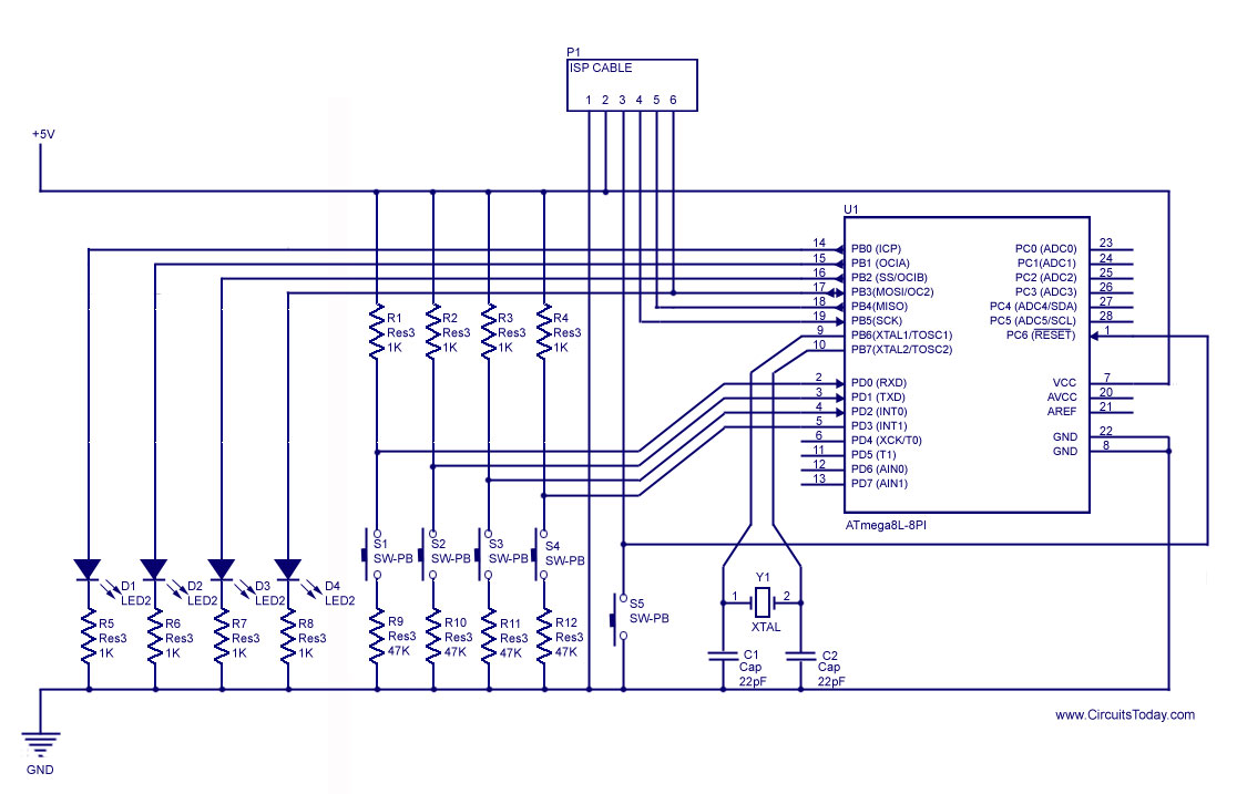
How to handle digital input/output (I/O) in AVR microcontrollers is explained using basic programs and circuits to illuminate an LED, generate a stepper motor sequence, read a push-button switch, and implement key debouncing. The handling of digital I/O in AVR...
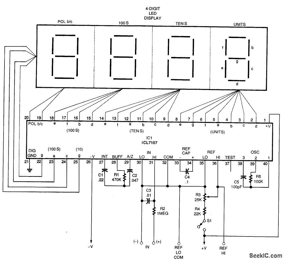
A basic digital voltmeter circuit utilizing the Harris Semiconductor ICL7107 is presented. It operates within a 2-V range. Calibration involves applying a known voltage of 1.2 V to the input and adjusting resistor R3 to achieve an accurate reading...
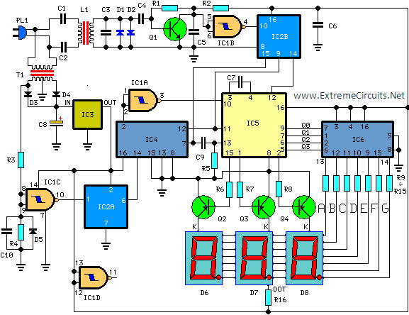
This circuit is designed for precise centigrade temperature measurement. It features a transmitter section that converts the sensor's output voltage, which is proportional to the measured temperature, into frequency. The output frequency bursts are transmitted through the mains supply...
This project involves a simple circuit designed to mix two or more audio channels into a single channel, such as converting stereo audio into mono. The circuit is capable of accommodating multiple input channels while maintaining low power consumption....
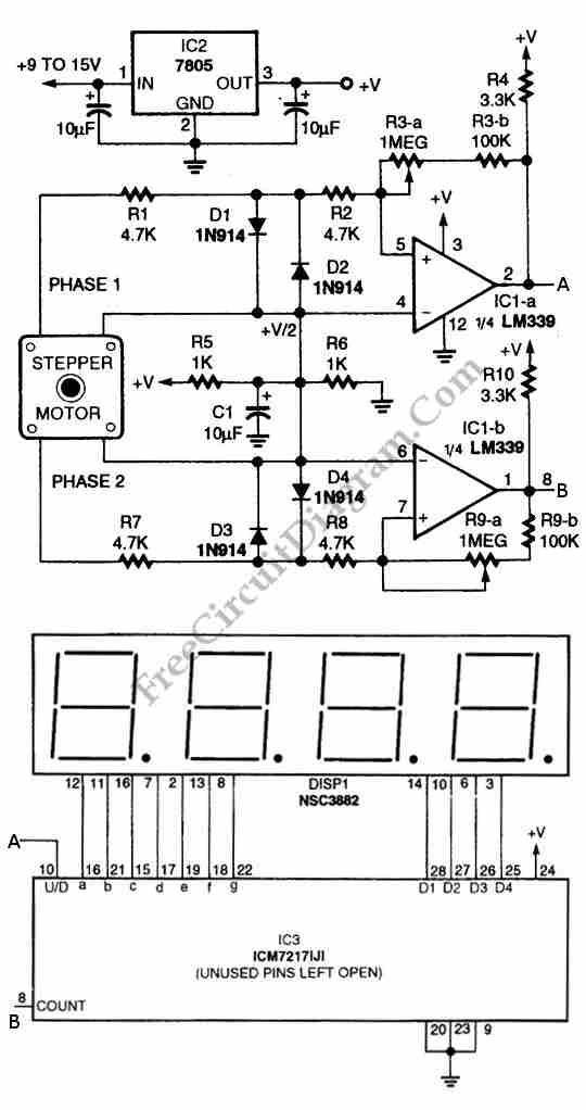
The circuit illustrated in the schematic diagram below allows for the visualization of the direction and shaft rotation of a stepper motor on an LED display. Instead of employing a digital rotation encoder as an input, this circuit utilizes...
A lot of friends asked me to draw a more shrunk circuit 2-ch mixer, which will contain also, operation CROSSFADER. The circuits can be modified and added also other channels, repeating basic that I give. It can be added...