
Analog to Digital Converter

The analog-to-digital (A-D) and digital-to-analog (D-A) conversion processes are fundamental in bridging the gap between continuous and discrete signal representations. An A-D converter samples an analog signal at specific intervals, quantizing its amplitude into discrete values. The process begins with the sampling of the signal, which is governed by the Nyquist theorem, dictating that the sampling frequency must be at least twice the maximum frequency present in the analog signal to avoid aliasing. Each sampled value is then quantized, typically using a fixed number of bits, which determines the resolution of the conversion. For instance, an 8-bit quantization yields 256 discrete levels, while a 16-bit quantization provides 65,536 levels, allowing for finer representation of the analog signal.
The quantization process introduces a quantization error, which is the difference between the actual analog value and the quantized digital value. This error can be minimized by increasing the number of bits used in the quantization process. Once the signal is quantized, it is encoded into a binary form, which can be easily processed and transmitted in digital systems.
Conversely, the D-A conversion process involves reconstructing the analog signal from its digital representation. This is achieved through a series of steps that include decoding the digital signal back into its quantized levels and then smoothing these levels into a continuous signal using a reconstruction filter, typically a low-pass filter. The filter helps to eliminate high-frequency components introduced during the quantization process, resulting in a smooth analog output that closely approximates the original signal.
Both A-D and D-A converters are critical components in various applications, including audio processing, telecommunications, and data acquisition systems. The choice of converter type and specifications depends on the application requirements, including bandwidth, resolution, and the nature of the signals being processed. Understanding the properties and limitations of both analog and digital signals is essential for designing effective signal processing systems that meet specific performance criteria.Before examining the various analog to d igital (A-D) and digital to analog (D-A) conversion processes it is useful to review the properties of each type of representation; in particular this may help select the representation most suited to the problem at hand. An analog signal is a signal whose value varies continuously with time, its instantaneous amplitude itself varying continuously within a limited range.
The simplest example is that of a sinusoidal signal Asin(w t + f ), whose instantaneous value covers all the values within the range (-A, +A). An analog signal may very often be expressed as a weighted sum of sinusoidal signals. The analog signal is a simple type of signal which can quite conveniently be transmitted, but its simplicity results in several drawbacks.
It is sensitive to parasitic signals and its amplitude or phase can be distorted by the transmitting system. When it undergoes such operations as analog multiplication the accuracy with which the signal is known is often reduced.
Moreover it is difficult to store an analog signal. On the other hand a digital signal usually appears as a series of symbols. Thus, in a binary system a signal consists of a series of numbers, each of which is 0 or 1, that may be given physical form by the absence or presence of pulses. It can be said that the signal is represented by a word of a given format that is of a given structure.
The digital signal represents the value of a quantity at a specific instant. It is not a continuous signal and since the symbols making up this signal (usually numbers) can only vary by `steps` the value represented by the signal must, perforce, be discrete. These difference from the analog signal, which may appear to be obstacles, are largely compensated by the advantages gained by the digital representation.
First of all a digital signal is far less sensitive to the imperfections of the transmitting system (distortion, noise) since it is only necessary to detect the pulses in order to obtain the information, their precise characteristics (amplitude, duration) not being taken into account. During the various operations the accuracy of the signal is maintained (if some of the truncating that is sometimes carried out is ignored).
On the other hand the pass band required for transmitting digital information is much greater than the pass band needed for an analog representation of the information. Thus, each representation has its advantages and disadvantages; the choice of one or other method must take into account the nature of the signal available, the possibility of introducing a digital process, the likelihood of transmitting the information, etc.
Information processing systems may be divided into analog systems and digital systems. In the first case the systems handle signals that vary in a continuous way whereas in the second case the systems handle discrete variables called digital numbers. Any digital treatment of an analog signal first requires an analog to digital conversion operation. If it is desired to recover the processed information in its initial analog form then the inverse conversion operation is needed.
It is necessary now to examine in some detail the operations required by the conversion processes. Let x(t) represent a given analog signal and let x*(t) be the series of discrete values of the given signal taken at regular time intervals of period Te. The operat 🔗 External reference
Related Circuits
The input mentions the 89S51/52 microcontrollers, but the accompanying image shows the 89C51. Clarification is needed regarding which microcontroller should be used with the provided .hex file without requiring changes to the file. The 89S51 and 89S52 are part of...
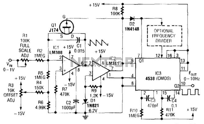
In this circuit, capacitor CI is charged to a fixed reference level and then discharged. The integrator IC1 charges CI until IC1 has a -6.2 V output, at which point comparator IC2 outputs a low signal. FET Q1 triggers...
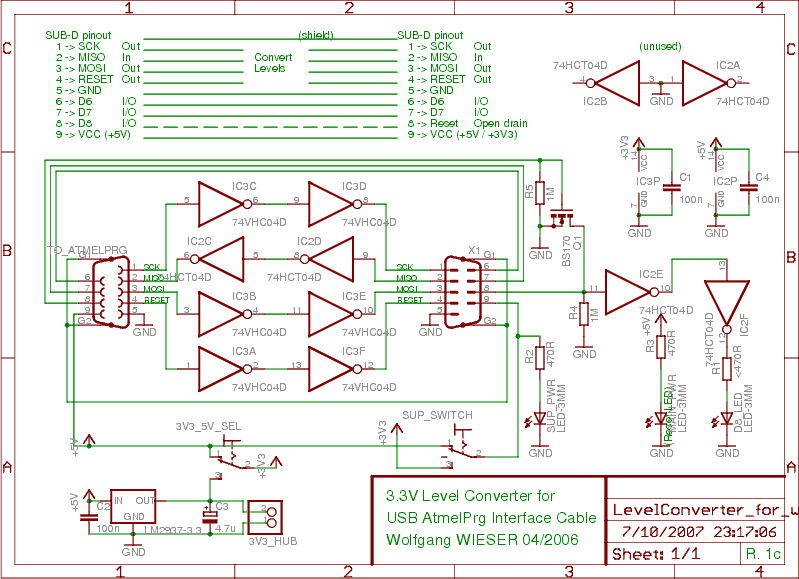
To program devices operating at 3.3V, such as SPI-based AVRs or JTAG-based CPLDs, level conversion is necessary for input and output signal levels. A 5V input may not register as HIGH at 3.3V, and a 3.3V device can be...
The reason for this project was to facilitate a quick installation for a local friend 10 km away, enabling the start of real-life testing to identify and resolve bugs and problems before releasing it to other users. The software...
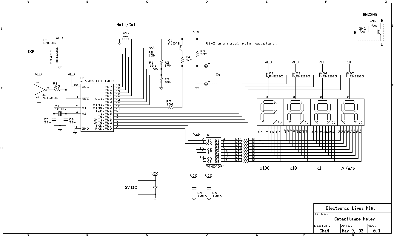
This is a simple capacitance meter which can measure capacitance value easy. There are some measurement methods for capacitance, at one time the capacitance was measured with a impedance bridge or a dip meter. Recently typical capacitance meters can...
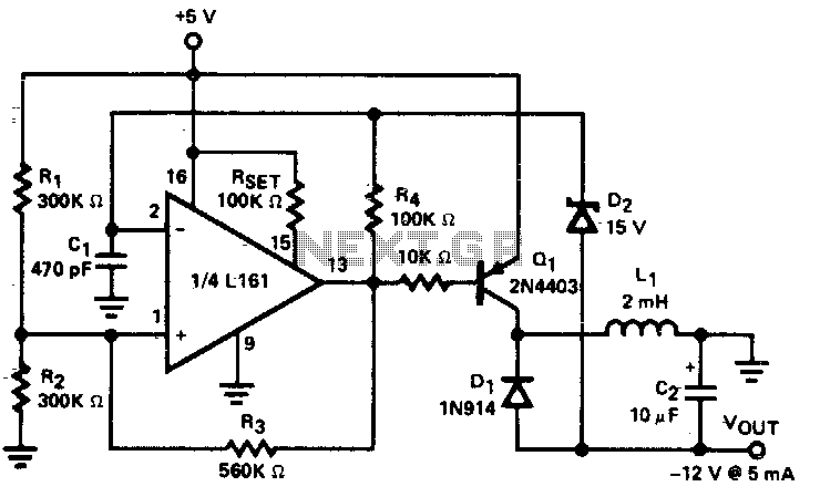
A low power DC to DC converter is created by integrating a flyback circuit with a square wave oscillator. The operating frequency is set at 20 kHz to reduce the size of the inductor (L1) and capacitor (C2). Regulation...