
Regulated DC-to-DC converter

The described low power DC to DC converter employs a flyback topology, which is a popular choice for applications requiring isolation and voltage step-up capabilities. The square wave oscillator generates a pulsating signal that drives the primary winding of the transformer, creating a magnetic field. As the current in the primary winding increases, energy is stored in the magnetic core of the transformer.
When the square wave signal transitions from high to low, the magnetic field collapses, inducing a voltage in the secondary winding. The output voltage is then rectified and filtered to provide a stable DC output. The choice of a 20 kHz operating frequency is critical, as it balances the trade-offs between efficiency, component size, and electromagnetic interference (EMI). The lower frequency allows for the use of larger inductors and capacitors, which can be more efficient but may increase the physical size of the components.
The Zener diode (D2) plays a vital role in regulating the output voltage. It maintains a constant voltage level by shunting excess current when the output voltage exceeds a predetermined threshold. This ensures that the output remains stable within the specified limits, even as the load conditions change. The converter is designed to provide a maximum output current of 5 mA before it drops out of regulation, indicating that careful consideration must be given to load requirements to maintain performance.
Overall, the integration of the flyback circuit with a square wave oscillator in this low power DC to DC converter design allows for efficient voltage conversion while maintaining compactness and reliability in various electronic applications.Low power dc to dc converter obtained by adding a flyback circuit to a square wave oscillator. Operating frequency is 20 kHz to minimize the size of LI and C2. Regulation is achieved by zener diode D2 Maximum current available before the converter drops out of regulation is 5 mA.
Related Circuits
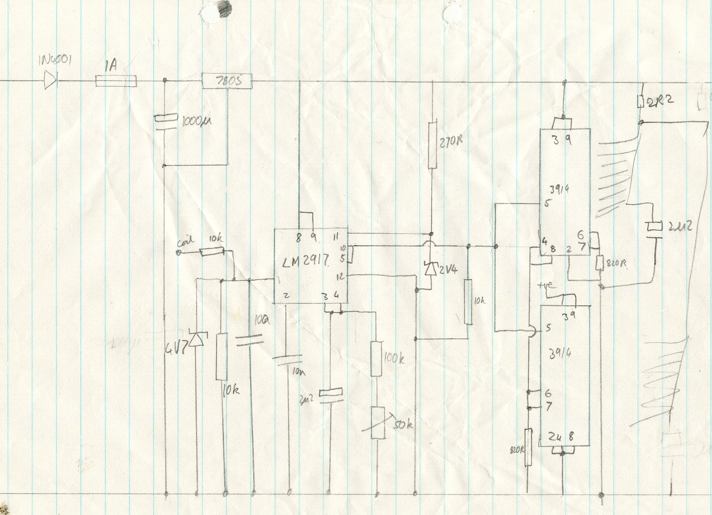
This circuit utilizes an LM2917 frequency-to-voltage converter. The input is connected to the low voltage side of the ignition coil, with various components designed to produce a full-scale output at 6000 RPM, corresponding to 12000 ignition pulses per minute,...
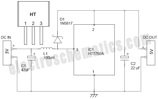
This document presents a straightforward and practical schematic for a 12V to 3V converter circuit. The output current of the circuit is approximately 1A. The 12V to 3V converter circuit is typically designed using a linear voltage regulator or a...
There are several methods to convert an AC voltage from a wall receptacle into the DC voltage required by a microcontroller. Traditionally, this has been accomplished using various types of power supply circuits. To convert AC voltage to DC voltage...
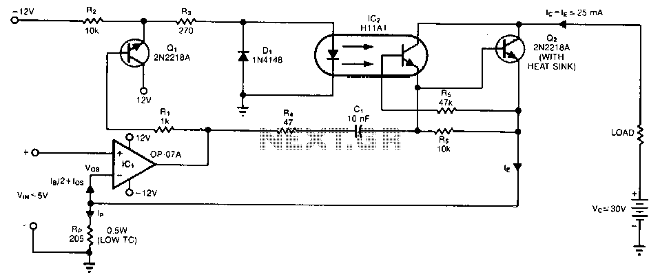
A single programming resistor (Rp) provides an output current range of approximately six decades. It is important to note that the temperature coefficient (TC) of this resistor can introduce potential errors, as it dissipates 125 mW when the junction...
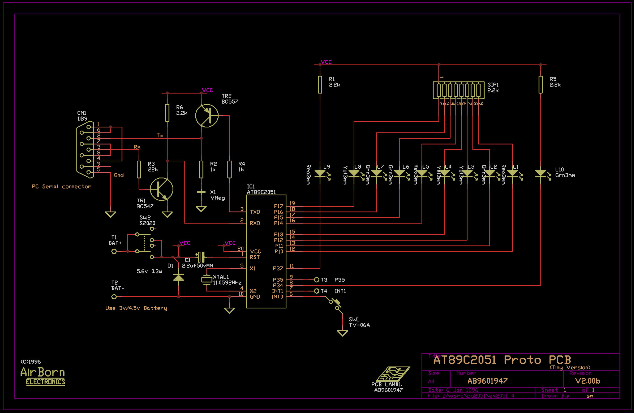
The example program included with the PG2051 evaluation kit is a basic serial to parallel converter written in 8051 assembler. This is probably a good example of the uses to which an AT89C2051 can be put - it would...

By configuring a comparator and a transistor to control the oscillator in a charge pump circuit, it is possible to generate a regulated output of virtually any desired value. Charge pump integrated circuits (ICs) can either invert or double...