
Analog video switch and amplifier with direct coupled output

The CA3256 circuit is designed to provide flexible switching and amplification capabilities across multiple channels. It features a direct-coupled output, which enhances the fidelity and speed of signal transmission, making it suitable for applications where minimal signal distortion is critical. The ability to select one of four channels in parallel with channel 5 allows for versatile signal routing, accommodating various configurations depending on the application requirements.
The digital control of the analog switches for channels 1 to 4 is implemented using a logic circuit, enabling precise selection and operation of the desired channel without the need for mechanical switches. This digital approach enhances reliability and reduces wear over time, which is particularly beneficial in applications requiring frequent channel switching.
Power supply requirements for this circuit stipulate a negative voltage (VEE) of -5 V, which is essential for proper operation of the CA3256 device. The positive supply voltage (Vcc) can be adjusted between +5 V and +12 V, allowing for compatibility with a range of systems and ensuring that the amplifier can operate efficiently within its specified limits.
The gain of the amplifier is adjustable through the use of an external feedback resistor (Rf). The relationship between the feedback resistor and the gain can be described by the appropriate gain equation, which should be referenced for accurate calculations. This feature provides flexibility in signal amplification, enabling the circuit to be tailored for specific signal levels as required by the application.
Overall, this circuit design offers a robust solution for applications requiring channel switching and amplification, with the added benefits of digital control and adjustable gain.This circuit shows a CA3256 switch/amplifier connected for a direct-coupled output. One of four channels can be selected in parallel with channel 5. The analog switches of channels 1 to 4 are digitally controlled by logic (Fig. 3-35B). A VEE of -5 V is required. Vcc can be from +5 to +12 V. Amplifier gain is determined by the external resistor Rf, as shown by the equaeion. 🔗 External reference
Related Circuits
The idea to produce a standard TV PAL signal using a SVGA graphics card was born a few years ago, where cheap graphics cards with TV output were still not available. To achieve a CCIR conform TV signal with...
The power supply circuits for servo systems are critical during both the adoption and operational stages. The power supply circuit for servo systems is designed to provide stable and adequate voltage and current levels necessary for the servo motors to...
The circuit has a flat frequency response from about 20Hz to well over 50Khz. Input sensitivity is 100mV for a full scale deflection on a 100uA meter. Built on two common emitter amplifiers, the first stage has a preset...
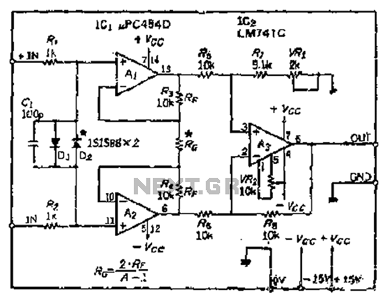
All resistance values are equal, resulting in the Cantonese operational amplifier's gain (A) being equal to 1. However, by selecting smaller resistances, the gain can be adjusted. The circuit can achieve the desired gain through six configurations. Two heavy...
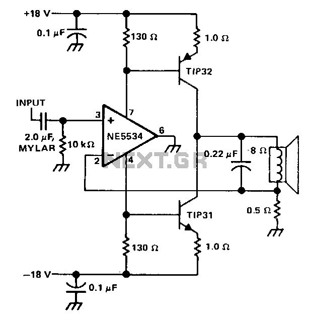
The single speaker amplifier circuit utilizes current feedback instead of the more commonly used voltage feedback. The feedback loop originates from the junction of the speaker terminal and a 0.5-ohm resistor, connecting to the inverting input of the NE5534...
Dynamic microphones utilize a moving coil within a magnetic field to convert mechanical movements into electrical signals. An ordinary mini speaker can be transformed into a... Dynamic microphones operate on the principle of electromagnetic induction. When sound waves hit the diaphragm...