
Analogue Audio Level Meter (VU meter)
")
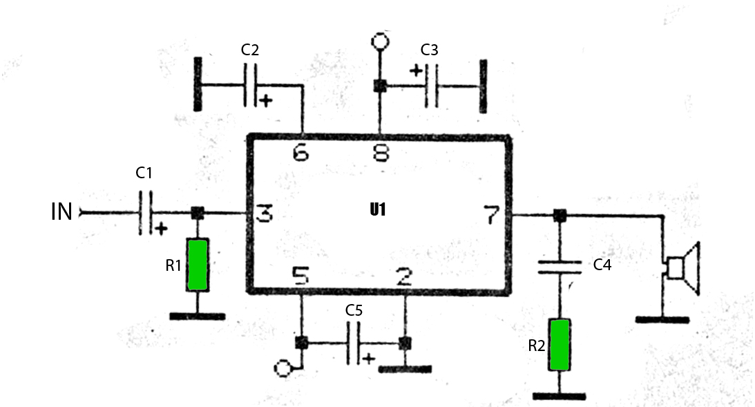
The circuit described utilizes a dual common emitter amplifier configuration to achieve a wide frequency response, making it suitable for audio applications. The frequency response spans from approximately 20 Hz to over 50 kHz, ensuring that it can accurately amplify audio signals across the audible range. The input sensitivity is set at 100 mV, which corresponds to full-scale deflection on a 100 µA meter, allowing for precise measurement of audio signal levels.
The first stage of the circuit consists of a common emitter amplifier, where a preset resistor is incorporated to allow for fine-tuning the full-scale deflection (FSD) of the meter. This adjustability is crucial for calibrating the circuit to different input signal levels, ensuring accurate readings. The design choice of using common emitter amplifiers contributes to high voltage gain, which is essential for amplifying low-level audio signals.
The final stage of the amplifier is biased to operate at approximately half the supply voltage. This biasing technique is employed to maximize the AC voltage swing, ensuring that the output signal can reach its peak values without distortion. Proper biasing is critical in amplifier design, as it affects the linearity and overall performance of the amplifier.
To handle audio frequencies effectively, a 10 µF DC blocking capacitor is included in the circuit. This capacitor allows AC signals to pass while blocking any DC offset, which could adversely affect the performance of the subsequent stages. Following the amplification stages, a full-wave bridge rectifier converts the amplified AC signal into a varying DC voltage. This conversion is necessary for the meter to display the instantaneous value of the audio signal.
It is important to note that the meter reading reflects an instantaneous value rather than a peak reading. This characteristic may limit the circuit's ability to capture transient peaks in audio signals, which may be relevant in certain applications where peak levels are critical. Overall, this circuit design effectively combines amplification, signal conditioning, and measurement in a compact and efficient manner.The circuit has a flat frequency response from about 20Hz to well over 50Khz. Input sensitivity is 100mV for a full scale deflection on a 100uA meter. Built on two common emitter amplifiers, the first stage has a preset resistor which may be adjusted for a FSD. The last stage is biased to operate at roughly half the supply voltage for maximum ac voltage swing. Audio frequencies are passed through the 10u dc blocking capacitor and the full wave bridge rectifier converts the signal to a varying dc voltage. Note that the meter reading is instantaneous and will not provide a "peak" reading. Audio levels c 🔗 External reference
Related Circuits
The car power amplifier utilizes the SI1050GL integrated circuit (IC) as the primary amplification component. It delivers an output power of 50 Watts at an 8-ohm mono impedance. The amplifier operates with a DC voltage of up to 25...
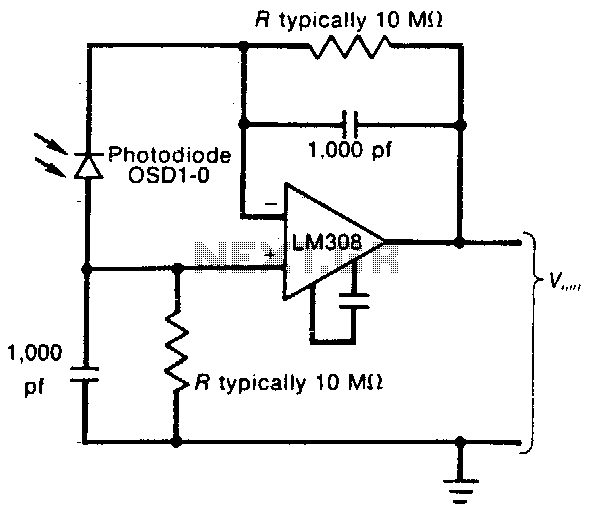
This circuit employs a low-input-bias operational amplifier (op amp) to provide a stable DC indication of light levels. To decrease the sensitivity of the circuit to light, the resistor Rl can be reduced, although it should not be set...
This is a design for a frequency meter based on AVR microcontrollers. Maximum input frequency is specified to be 30 MHz in the multi-chip configuration, and in single-chip configuration, there are both 5 MHz and 10 MHz versions operating...

The Kelvin scale version reads from 0 to 1999 K theoretically, and from 223 K to 473 K actually. The 26 kΩ resistor brings the input within the ICL7106 common-mode voltage range; two general-purpose silicon diodes or an LED...
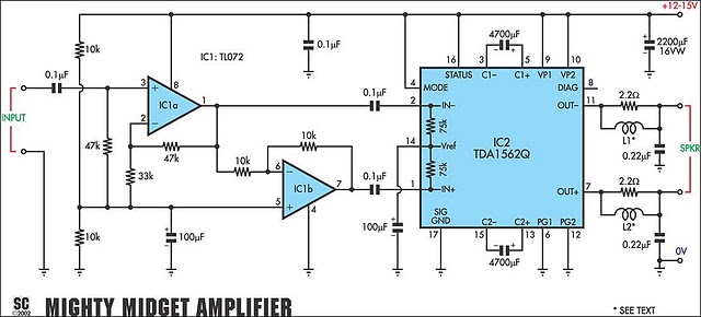
It is based on a Philips class-H audio amplifier integrated circuit and can deliver 36W RMS or 70W music power, all from a 13.8V supply. The new Mighty Midget Amplifier can produce approximately 36W RMS continuously into a 4-ohm...
The following circuit presents a schematic diagram for a one-transistor FM radio with enhanced audio gain. Features include a super-regenerative design. The one-transistor FM radio circuit utilizes a super-regenerative architecture, which is known for its simplicity and efficiency in receiving...