
Analog Voltage Camera-Image Tracker

The circuit utilizes an RS-170 camera, which is a standard video format camera, to capture images and detect the position of objects based on their color contrast against the background. The process begins with the camera outputting a video signal that is processed by the integrated circuits (ICs) in the circuit.
IC2A and IC2B are configured to establish a valid video gate, ensuring that the downstream components only receive valid signals during the active video period. This gating is crucial because it prevents IC3 from processing erroneous signals that could occur during the vertical blanking interval, where the camera is not actively capturing image data. This mechanism avoids false readings that could compromise the accuracy of the object detection.
IC4 is designated as a black level detector. It continuously monitors the video signal for the presence of a black object, specifically checking the luminance levels in the center of each video line. The detection of a black object is determined by comparing the signal level against a predefined threshold. When a black object is identified, it triggers a response in the subsequent circuitry.
IC5 acts as a latch for the output from the comparator, which is likely integrated within IC4. This latch captures the momentary state of the black level detection and converts it into a square wave output. The duty cycle of this square wave is directly proportional to the location of the detected black level within the video frame. Thus, the width of the pulse can be interpreted to ascertain the position of the object being monitored.
The integration and buffering of the analog output voltage are accomplished by R1, C1, and IC6. R1 (a resistor) and C1 (a capacitor) form an RC network that smooths the output signal from IC5, converting the square wave into a more stable analog voltage. IC6, which is likely an operational amplifier or buffer, further stabilizes this voltage for use in downstream applications, ensuring that the output can be reliably used for further processing or control tasks.
Overall, this circuit is designed to effectively detect and track objects based on their visual characteristics, particularly focusing on the presence of black objects against varying backgrounds, making it suitable for applications in automation, robotics, and surveillance systems. By using a low-cost RS-170 camera and this circuit, a voltage that trades the position of an object in the field of view of a camera is generated. IC2A and IC2B form a valid video gate that holds IC3 in reset during the internal vertical blanking to prevent false interpretation of the UBI as black video. IC4 is a black level detector. The circuit tests for a black object in the middle of each video line. IC5 latches the comparator"s output and produces a square wave whose duty cycle depends on where the black level is detected in the video field.
Rl, CI, and IC6 integrate and buffer the analog output voltage.
Related Circuits
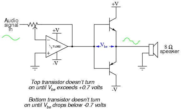
This project is an audio amplifier designed to amplify output signals from small radios, tape players, CD players, or other audio signal sources. For stereo operation, two identical amplifiers must be constructed—one for the left channel and another for...
The current source in the diagram reacts very quickly to changes in the input signal and may be utilized in specific measurements. The differential amplifier IC1 ensures that the voltage across resistor R2 is equal to the input voltage,...
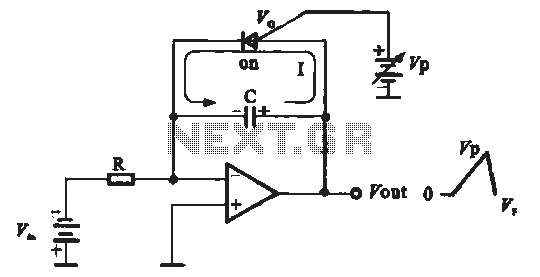
A sawtooth voltage-controlled oscillator operates by first generating a negative potential maximum at the output of the comparator. This output is then fed to the inverting input terminal through resistor R1, which is part of the relaxation oscillator. The...
The Traynor YBA-1 is closely related to the classic Bassman/JTM-45 circuit. A vintage '67 model was acquired, which was in excellent condition except for a poorly executed reversible master volume modification and a burnt power transformer. This version features...

Figure 1 illustrates a circuit that utilizes a single +V power supply and a voltage output Digital-to-Analog Converter (DAC) known as the AD5620. The DAC is controlled via an SPI port, with its output ranging from 0 V to...
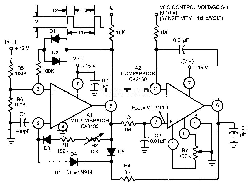
This circuit utilizes a CA3130 BiMOS operational amplifier as a multivibrator and a CA3160 BiMOS operational amplifier as a comparator. The oscillator exhibits a sensitivity of 1 kHz/V, with a tracking error of approximately 0.02% and a temperature coefficient...