
Analogue Inputs to MIDI Out

This device is designed for seamless integration into MIDI control systems, providing a flexible solution for a variety of applications requiring analog input conversion to MIDI signals. The analog inputs can be utilized for various sensor types, enhancing versatility in interfacing with different hardware components. The use of potentiometers allows for precise control over MIDI parameters, making it suitable for musical instruments and performance applications.
The programming mode facilitates easy customization of the MIDI output, allowing users to adjust the range values to match their specific needs. The internal EEPROM ensures that settings are retained, which is crucial for applications where consistent performance is required after power interruptions. The scanning of analog inputs in Normal mode ensures that real-time data is transmitted efficiently, maintaining responsiveness in live performance scenarios.
Proper grounding of unused inputs is critical in minimizing noise interference, which can affect the integrity of the MIDI signals. This design consideration enhances the reliability of the device in various environments, particularly those with potential electromagnetic interference.
Overall, this device provides a robust framework for converting analog signals into MIDI commands, offering flexibility, reliability, and ease of use for electronic musicians and developers alike.This allows up to 8 analogue inputs (with a range from 0 to 5 volts) to produce selectable MIDI control output commands. The analogue inputs could be rotary or slider potentiometers which are connected to 0 to 5 volts. Also the inputs could be connected to Force Sense Resistors (FSR), Light Dependent Resistors, Magnetic hall effect sensors via suit
able interfacing etc. Note that unused inputs should be grounded to the 0 Volt line to prevent spurious noise pickup. At power-on, if the Menu switch is simultaneously held ON, then the unit will enter programme mode. Then each push of the menu switch moves through the menu. The menu consists of the following: Programming the Analogue to MIDI Unit only has to be done once and the range values are stored internally in the EEPROM and the unit will continue to operate in this mode, even when power is removed, until reprogrammed. In Normal mode the 8 analogue inputs are scanned and the corresponding MIDI controller data is transmitted on a particular MIDI channel.
The MIDI channel has a range from 1 to 16 and the controllers range from 0 to 121 as shown in table 1. 🔗 External reference
Related Circuits
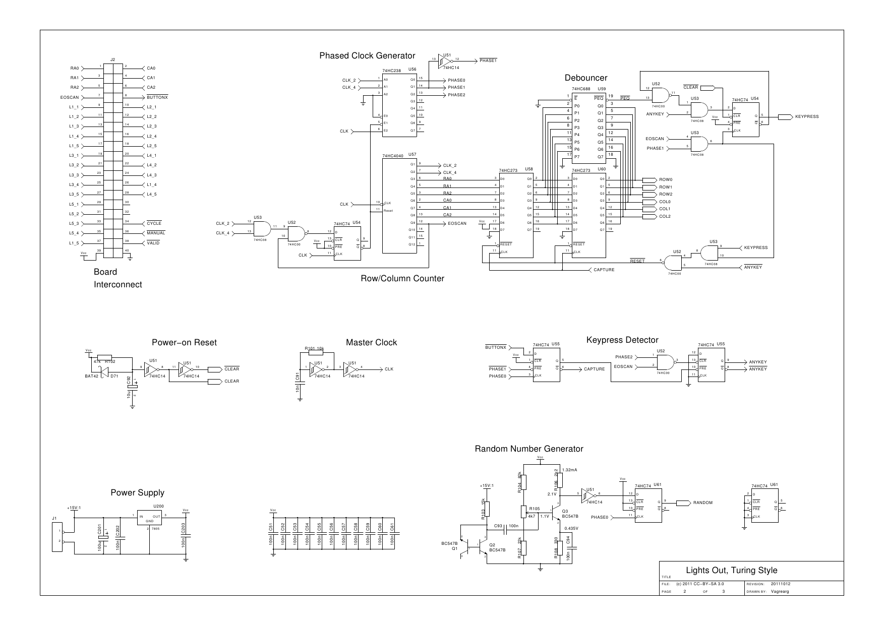
The design is based on the previous analysis of calculating the game in a circular shift register. While designing, it was realized that small extensions to the design would enable additional gameplay features, such as replay and manual input....
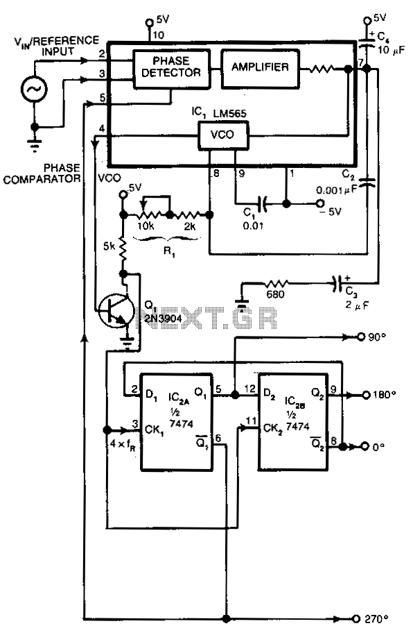
Many applications require control signals that have phase shifts relative to an input signal. This circuit accepts a sine, square, or triangular wave as an input reference signal and produces square-wave outputs with 0°, 90°, 180°, and 270° phase...
It is essential to implement current limiting when charging batteries. Open frame linear power supplies can be used for this purpose, with the current limit set to the recommended charging current of the battery. Foldback current limiting is particularly...
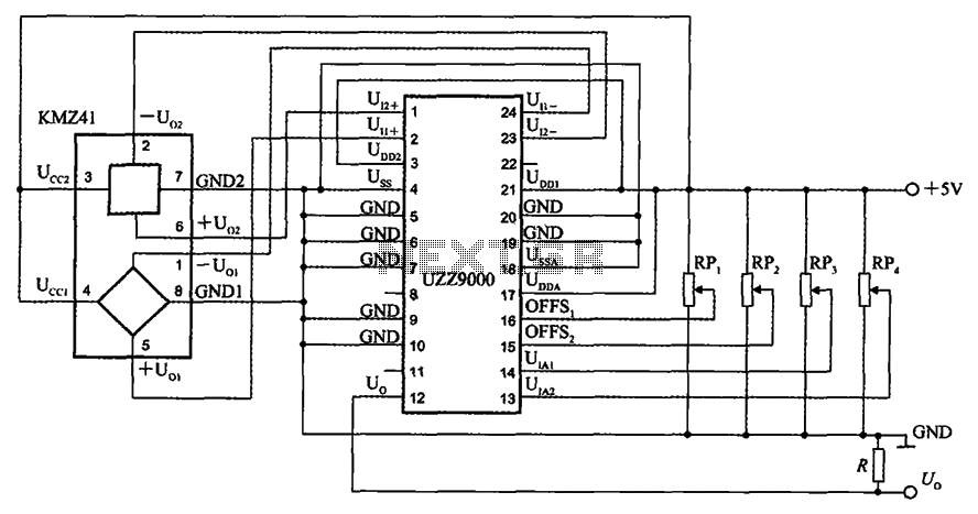
The UZZ9000 KMZ41 detection circuit is configured based on the voltage output type and angle. It operates with a +5V power supply. Potentiometers RP1 and RP2 are used for offset voltage adjustment, while potentiometers RP3 and RP4 are utilized...
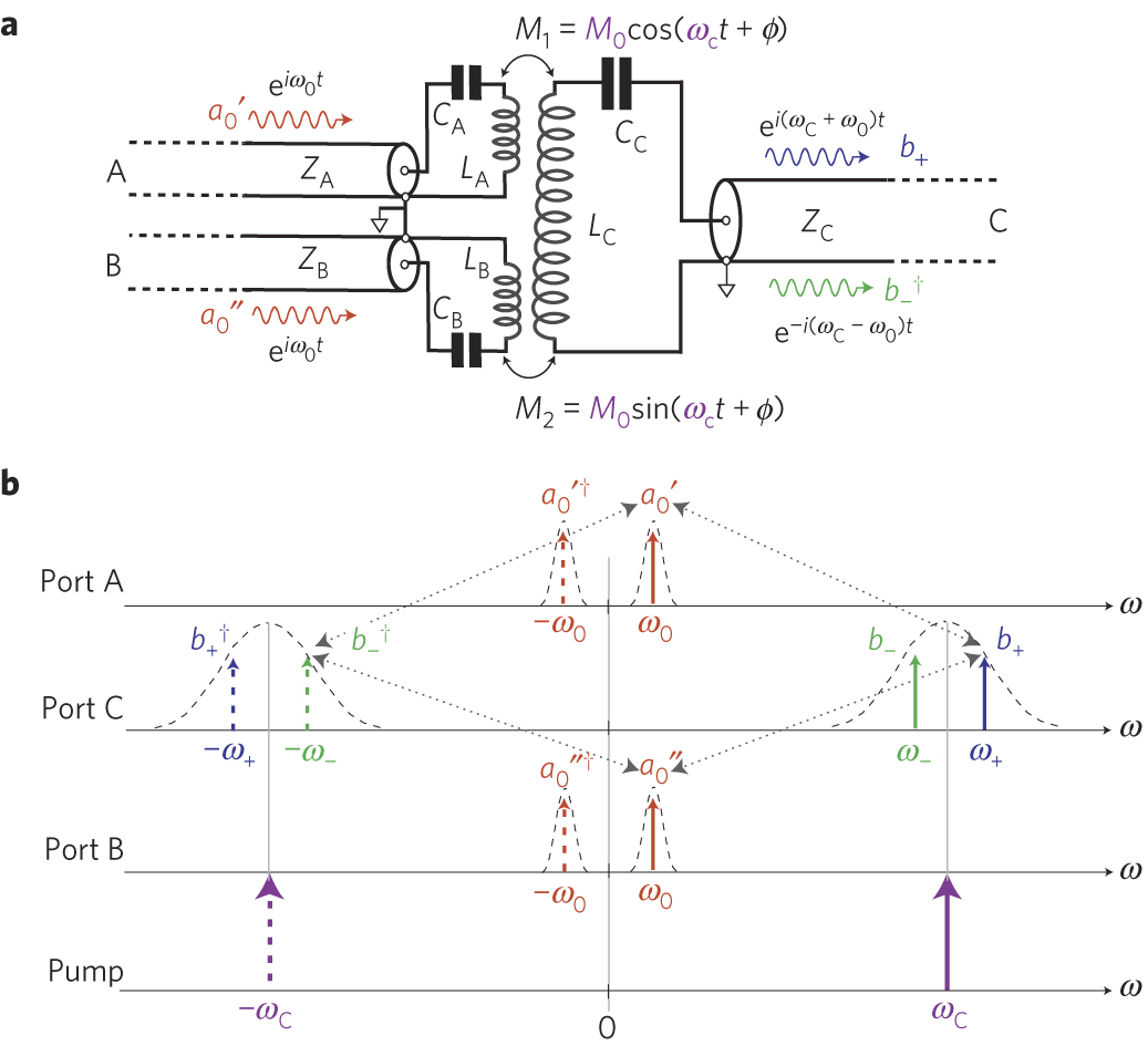
The circuit schematic of the UDC consists solely of dispersive components. Two low-frequency series LC resonators, with equal inductances (LA=LB) and capacitances (CA=CB), are connected to two input semi-infinite transmission lines, designated as A and B. These resonators are...
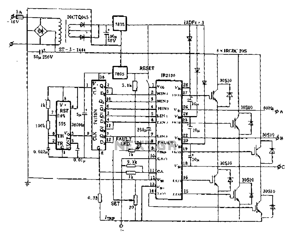
The application of the aforementioned advantages allows the IR2130 to be effectively utilized for DC cut crossing speed, DC servo systems, three-phase power inverters, and switching power supplies. Additionally, it is applicable in inverter power supplies, uninterruptible power supplies...