
Answering Machine Beeper

The described circuit utilizes a photoresistor (Rl) to detect the blinking light of an answering machine. The operation begins when the LED of the answering machine emits light, which is sensed by the photoresistor. As the light intensity varies with the blinking LED, the resistance of Rl decreases in response to the increasing light, allowing current to flow through it. This change in resistance is crucial as it influences the charging of a timing capacitor connected to timer U1.
Upon detecting sufficient light, the timer U1 is activated. It is configured to produce a short output pulse, specifically lasting 0.2 seconds. This pulse is generated through the internal circuitry of the timer, which may be set up in monostable mode, where it remains in a stable state until triggered by the input from the photoresistor.
The pulse output from U1 is then used to activate a buzzer (BZ1). The buzzer serves as an audible alert, signaling that the answering machine has received a message. The integration of Rl with the LED ensures that the system is responsive only when the answering machine is in use, thereby preventing false triggers from ambient light.
Additionally, the design incorporates light shielding measures to prevent interference from other light sources. This shielding ensures that the photoresistor only reacts to the specific light output of the answering machine's LED, enhancing the reliability of the circuit. Overall, this schematic exemplifies a simple yet effective method of integrating optical sensing with timer-based output to create a functional notification system. When the light on the answering machine blinks, the resistance of photoresistor Rl charges, triggers the timer (Ul ), and generates 0.2-s pulse that activates BZ1. Rl is optically coupled to the LED on the answering machine and is properly light shielded.
Related Circuits
This circuit is not highly critical and can utilize various devices (such as a tape player with a message recorded on an endless tape) that do not overload the circuit or the telephone line. The incoming line is safeguarded...
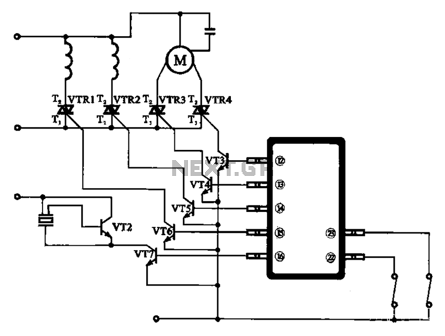
The schematic for the automatic washing machine motor driver outlines the motor drive circuit for the Narcissus XQB30-III-type washing machine. The control circuit comprises four Triacs, four drive transistors, and a control chip. This setup allows for the activation...

The INA321/322 forms a low-cost, medium-accuracy ECG amplifier circuit. The INA321 receives input signals from the patient's arm, amplifying them before sending the modified output to the operational amplifier OPA336. The OPA336 generates an output voltage from the inverting...
This circuit is designed for alerting purposes after a predetermined time has elapsed. It is ideal for tabletop games that require a fixed duration for answering questions or moving pieces. In this context, it serves as a modern alternative...
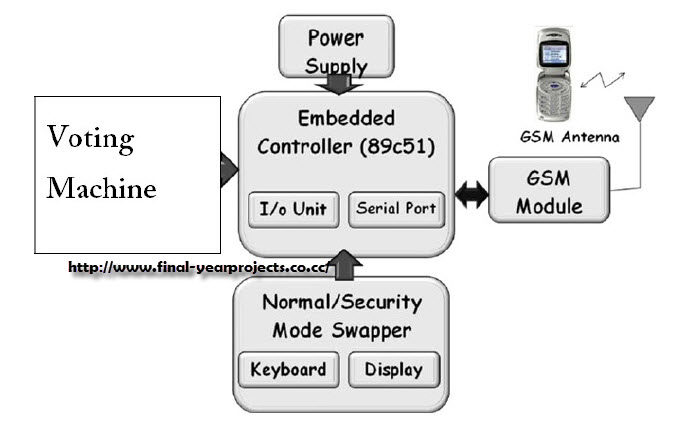
This project involves a GSM-based voting machine system that utilizes AT commands to send SMS through a microcontroller. It operates in two modes: Normal mode, where an authorized individual from a local area can cast their vote, and Security...
Nowadays electronic voting machines are being used effectively. The confidence of the voter in its flawless working is gradually building up and these machines are thus becoming quite popular throughout the country. Features of the electronic voting machine include...