
GSM Based Voting Machine System ECE Project Report

The GSM-based voting machine system is designed to streamline the voting process using mobile communication technology. The system is built around a microcontroller, which serves as the central processing unit. It interfaces with a GSM module that is responsible for sending SMS messages containing the votes cast by users. The GSM module communicates with the microcontroller through a serial interface, typically utilizing UART (Universal Asynchronous Receiver-Transmitter) for data transmission.
In Normal mode, the system restricts voting to authorized users within a specified local area. This is achieved through a user authentication mechanism, which may involve the use of unique identification numbers or passwords. The microcontroller processes the input from the voting machine, validates the user, and sends the vote via the GSM module.
In contrast, Security mode allows for a broader participation, where any registered voter from across the country can cast their vote. This mode may require additional security measures, such as encryption of the SMS data and validation of the sender's phone number to prevent unauthorized voting.
The voting machine is equipped with a user interface, which may include buttons for input and an LCD display to provide feedback to the user. The power supply unit ensures that the entire system operates reliably, providing the necessary voltage and current levels for the microcontroller and other components.
The block diagram of the system provides a visual representation of the interconnections between the components, illustrating how the microcontroller, GSM module, and voting machine interact. The circuit diagram included in the report details the electrical connections and component specifications, serving as a valuable resource for students and engineers interested in replicating or modifying the system.
Overall, this GSM-based voting machine project exemplifies the integration of telecommunications and electronics, showcasing how modern technology can enhance democratic processes. The comprehensive documentation provided, including programming details, enables users to understand and implement the system effectively.This is a good Electronics & communication project on GSM Based Voting Machine System which uses AT commands to sens SMS through Microcontroller. The project has 2 modes viz. Normal mode and Security mode. In normal mode an authorized person of a local area can vote and security mode is any one from the whole country can vote.
The project require a GSM module, a voting machine connected to Microcontroller, power supply etc. You can also Subscribe to FINAL YEAR PROJECT`S by Email for more such Projects and Seminar. The above image shows the block diagram of GSM Based Voting Machine System and its components. The report contains the circuit diagram and microcontroller programming for students. You can use this report for your reference and study. 🔗 External reference
Related Circuits
There is, and always has been, a marked lack of good, inexpensive lighting controllers for small theatre groups or musicians. The LX-800 Lighting System was designed with these applications in mind. More: As I said, this is an ambitious...
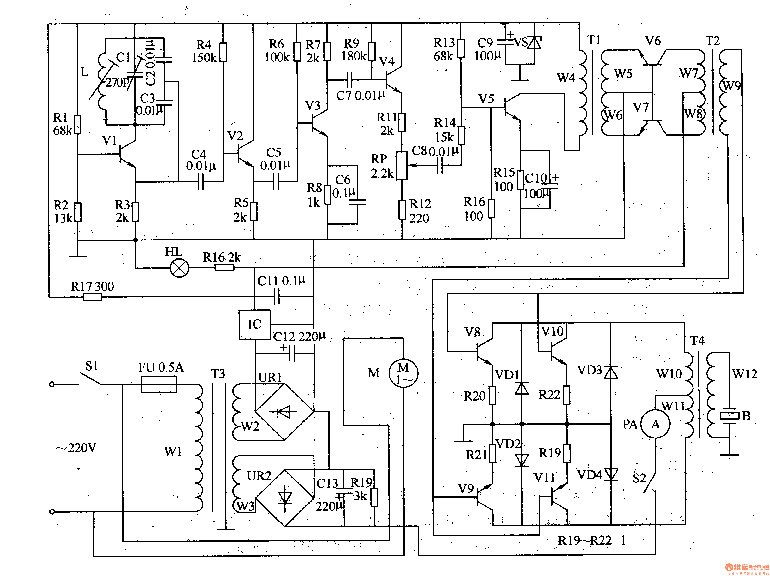
The circuit comprises a power supply circuit, an ultrasonic oscillator circuit, a pre-amplifier, an amplifier, and a power amplifier drive output circuit. The power supply circuit includes a power switch (S1), a fuse (FU), a power transformer (T1), a...
The 82C55 and seven-segment decoders on the display board will be replaced with a set of shift registers to eliminate the need for the 82C55 and the extensive wiring. The ADC0804 will be substituted with a serial interface ADC...
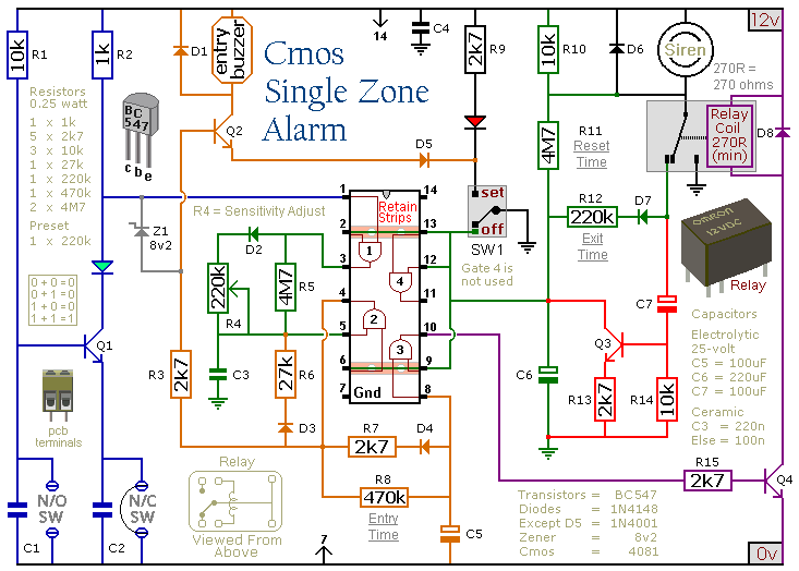
This circuit includes automatic exit and entry delays, a timed bell cut-off, and a system reset feature. It is designed to support both normally-open and normally-closed switches and can accommodate standard input devices such as pressure mats, magnetic reed...
A small Tesla Coil (12-inch range), Jacob's Ladder, or an "Antigravity Project" from the book "Electronic Gadgets for the Evil Genius" is being discussed, but sourcing parts for these projects has proven challenging. The book is informative, yet the...
The following circuit illustrates the sensor circuit diagram for automatic room lights. This circuit is based on the CD4017 integrated circuit (IC) and features the use of two light-dependent resistors (LDRs). The automatic room light circuit utilizes the CD4017 decade...