
ANTENNA DESIGN FOR FM TRANSMITTER

This configuration describes a basic antenna system utilizing two aluminum rods as the radiating elements. The rods serve as a dipole antenna, where each rod acts as one half of the dipole. The insulator between the rods is crucial as it prevents electrical contact, ensuring that the two rods operate as separate conductive elements.
The choice of a 75-ohm cable is standard for television antennas, as this impedance matches the typical input impedance of many TV tuners, optimizing power transfer and minimizing signal reflections. The central feed point is where the coaxial cable connects to the antenna, typically at the junction of the two rods. This connection point is critical for the performance of the antenna, as it influences the radiation pattern and impedance characteristics.
To ensure effective operation, the length "L" of each aluminum rod should be approximately half the wavelength of the target frequency for which the antenna is designed. The formula to calculate the resonant frequency (f) based on the length of the dipole antenna is given by:
\[ f = \frac{c}{2L} \]
where \( c \) is the speed of light, approximately \( 3 \times 10^8 \) meters per second. This relationship indicates that the antenna will be most effective at resonating at frequencies where the length of the rods corresponds to the wavelength of the radio waves.
In practical applications, the installation height, surrounding environment, and orientation of the antenna will also significantly affect its performance. Proper grounding and weatherproofing of the aluminum rods and connections can enhance durability and signal quality, making this antenna design suitable for various applications, including receiving broadcast television signals.Two aluminum rods, each of length "L" in meters are joined together through an insulator as shown in fig. From center, 75 ohm cable is feeded just like ordinary TV antenna. 🔗 External reference
Related Circuits
All ATL-3 loop windings are center-tapped and balanced with respect to their amplifier/receiver chassis ground, which leads to self-cancellation of electric field interference. Magnetic noise fields, such as those from televisions and electric meter boxes, or electromagnetically radiated interferences,...

A standard 12-volt automotive electrical system can be viewed as a robust yet unreliable source of low-voltage DC current. Any mobile PC installation should encompass several features, as automotive systems must adhere to strict electrical standards. The starter motor...
This amplifier is designed for outdoor installation and is connected to an indoor power line box. It utilizes either 50-ohm or 75-ohm coaxial cables for the connection between indoor and outdoor units. The amplifier circuit board is depicted in...
This application note details the design of a 50-watt, isolated, forward converter, utilizing the MAX8540 synchronizable, high-frequency, current-mode PWM controller. The schematic design of the 50-watt isolated forward converter using the MAX8540 involves several key components and stages to ensure...
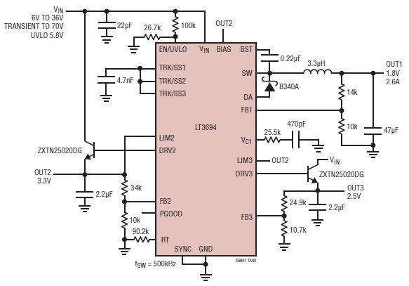
The LT3694 is a monolithic, current mode DC-DC converter that can be designed as a simple step-down converter, supporting a maximum output current of 2.6 A. This switching step-down converter is capable of generating up to 2.6 A at...
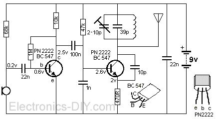
The FM transmitter is a simple and compact device with a transmission range of 100-150 meters, offering good sensitivity and low current consumption. The schematic of the transmitter includes a bass amplifier for the first transistor and a frequency...