
Mini FM Transmitter

The FM transmitter circuit is designed to operate within a specified frequency range, typically between 88 MHz and 108 MHz, which corresponds to the FM radio band. The bass amplifier stage enhances the audio signal before it is modulated onto the carrier frequency. The choice of transistors is critical; they must be capable of handling the required current and frequency range. The first transistor acts as a pre-amplifier, boosting the input audio signal, while the second transistor functions as an oscillator, generating the RF signal.
The transitional capacitor plays a vital role in frequency stability and modulation depth. Its value can be adjusted to fine-tune the transmitter's output frequency, allowing for precise control over the signal. The PCB layout is optimized for minimal interference and includes clearly marked component values to facilitate assembly and troubleshooting.
The use of enameled wire for the antenna is advantageous due to its durability and ability to withstand environmental factors. The specified 40 cm length is chosen to match the desired frequency, ensuring efficient radiation of the RF signal. The low current consumption of approximately 10 mA is achieved through careful selection of components and circuit design, making the FM transmitter suitable for battery-powered applications.
In summary, the FM transmitter is a well-engineered device that combines simplicity and efficiency, making it an ideal choice for hobbyists and educational projects. Its compact design and clear schematic representation allow for easy assembly and modification, while the use of modern components ensures reliable performance.FM Transmitter is very simple, compact, and has transmission signal with a range of 100-150m, good sensitivity and low current consumption. Transmitter`s schematic consists of a bass amplifier for the first transistor and the proper frequency generator in the second.
FM Transmitter divided transitional capacitor that allows you to set up a cascade separately. Transmitter PCB shows the value of all the details and transistors! Reel contains 5 turns enameled wires 0. 35mm to send a diameter of 3. 2mm (rod of the handle). Setting frequency boils down to the installation shown in the pattern of voltages through appropriate resistors, and then check the current consumption ½ it should be about 10mA antenna ½ a piece of wire 40cm. Here you can see the bug assembly factory performance. FM Transmitter uses very small PCB and some SMD resistors. 🔗 External reference
Related Circuits
This schematic represents a tone transmitter. When using sufficiently small resistor values, it generates a tone. A resistive microphone (such as a carbon microphone) can be placed in parallel with or replace the resistor, allowing modulation of the tone...

This FM transmitter project is a simple yet effective circuit capable of transmitting signals over a distance of up to 1 kilometer in open air conditions. The circuit employs an RF transistor in the output stage, along with two...
An FM radio generates an interference signal that can be detected on another FM radio tuned 10.7 MHz higher than the original. A 50 kΩ potentiometer is used to adjust the modulation level to its maximum without introducing distortion....

The TV transmitter described here is capable of transmitting audio and video signals from satellite television receivers, VCD players, and video recorders through an open circuit. It can also receive signals using open antennas. This device is ideal for...
Mark the entire scale with the standard metronome steps as follows: 40, 42, 44, 46, 48, 50, 52, 54, 58, 60, 63, 66, 69, 72, 76, 80, 84, 88, 92, 96, 100, 104, 108, 112, 116, 120, 126, 132,...
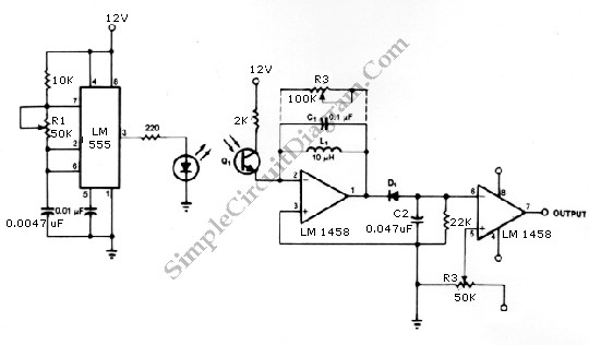
The infrared transmitter and receiver circuit depicted in the schematic diagram below can function as a remote control. The transmitter primarily operates as an oscillator. The infrared transmitter and receiver circuit is designed to facilitate wireless communication through infrared signals,...