
Anti-saturation function delete circuit schematics

The UAA4002 integrated circuit is utilized in applications requiring precise control of switching transistors. The removal of anti-saturation devices simplifies the circuit design while maintaining operational efficiency. The automatic adjustment of the base current ensures that the switching transistor can respond dynamically to varying load conditions, which is essential for maintaining optimal performance in power applications.
In this configuration, the CE pin diode plays a critical role in managing the voltage levels across the power transistor. By connecting the CE pin directly to the collector of the power transistor, the circuit minimizes the risk of saturation. The resistor used to connect Vcc to the CE and V+ pins helps to regulate the voltage supplied to the driving circuit, ensuring that the transistor remains in the desired operating region.
The design choice to operate the power transistor in saturation is particularly advantageous at low frequencies, where switching losses are minimal. This approach reduces overall power dissipation and enhances the efficiency of the system. The low conduction losses that arise from this configuration can be attributed to the inherent characteristics of the power transistor when it operates in the saturation region.
Overall, this circuit design demonstrates a sophisticated approach to managing transistor operation in power electronics, emphasizing efficiency and reliability while addressing potential saturation issues through careful component selection and configuration.Anti-saturation devices deleted: UAA4002 routine applications, switching transistor transistor (switching transistor driven) base current is adjusted automatically, driven powe r transistors in the critical saturation, but driven transistor operating frequency when the rate is very low, the switching losses were insignificant, then the losses are mainly low conduction losses due to artificially remove and anti-saturation network, that has been driven through the power transistor operating in saturation. Way to achieve this purpose is twofold: First, the UAA4002V CE pin diode is driven off the power transistor collector, and directly to the y CE pin and V + pin is connected through a resistor after the pick vcc (see Fig.
12-28), such an approach is that the drawbacks encountered by the driving transistor can not be saturated after the rapid and effective protection,
Related Circuits
The GH-75 type circuit is a hydrogen atom welder that utilizes hydrogen bonding without melting the workpiece. This process involves the use of a tungsten electrode to generate an electric arc, which effectively welds the workpiece in a hydrogen-protected...
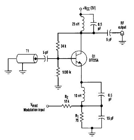
This varactorless high-frequency modulator electronic project must be powered by a simple DC 3-volt power source, such as a 3-volt battery. Traditionally, high-frequency oscillators are frequency-modulated using a varactor. However, varactors typically require a significant voltage change to achieve...
Using this low cost project, one can reproduce audio from a TV without disturbing anyone. It does not use any wire between the TV and headphones. Instead of a pair of wires, it uses invisible infrared light to transmit...
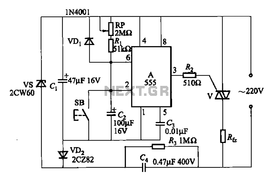
A 555 four-base integrated circuit delay circuit is designed to facilitate a transition from high to low output. When the button SB is pressed, the output is set to high, and after a specified delay, the output transitions to...
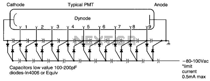
A Cockcroft-Walton voltage multiplier provides the necessary stepped voltage for the dynodes of the photomultiplier tube (PMT) without the use of a power-wasting voltage-divider resistor, which is typically employed in traditional configurations. The Cockcroft-Walton voltage multiplier is a type of DC-DC...
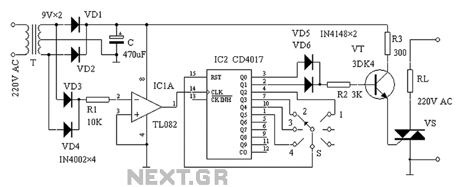
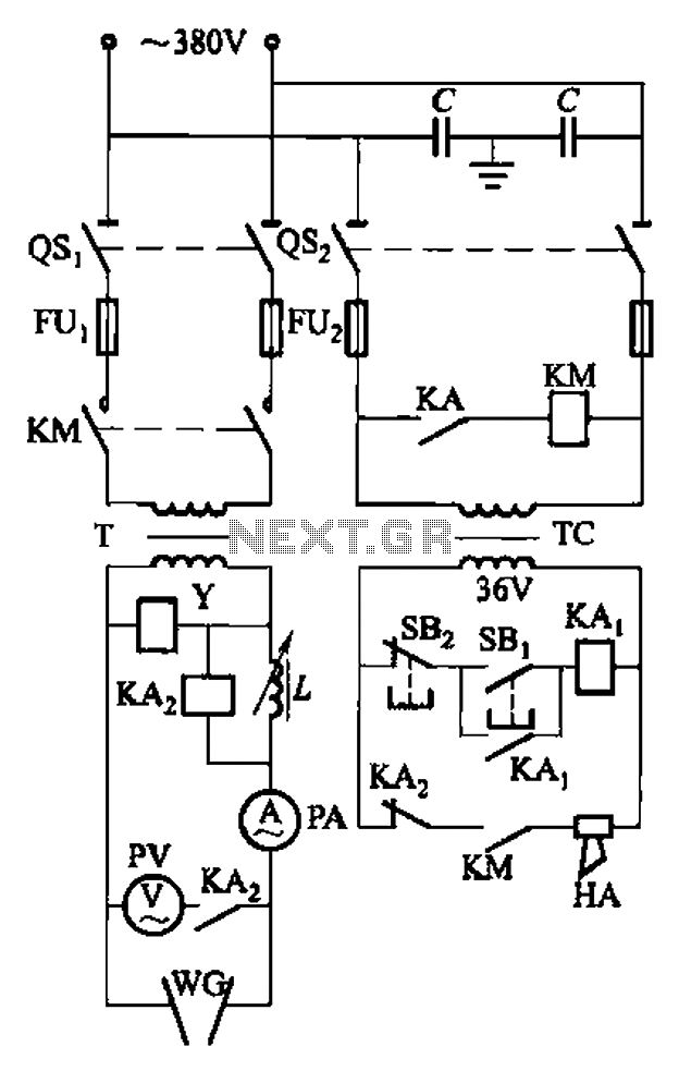
The zero-power regulator circuit is simple, reliable, and functional. It is suitable for various electric power adjustment applications, such as series-wound motor power adjustment. The operational principle of the circuit involves several components, including the power circuit, an AC...