
Anti-theft Alarm Of Motorcycle One

The circuit operates by utilizing a trigger mechanism to detect specific conditions, such as movement or changes in environmental parameters. The mercury switches (S1) function as the primary sensing elements; when the switch is tilted or moved, it closes the circuit, allowing current to flow. This action activates transistor (V1), which in turn energizes relay (K1). The relay serves as a switching device that can control higher power loads, such as an alarm system.
The alarm control circuit is responsible for processing the signal from the trigger circuit. Relay contacts (K1, K1-1, K1-2) are utilized to manage the flow of current to the alarm system. The transistor (V2) amplifies the signal received from the relay, ensuring that the alarm is activated with sufficient power. Resistors (R3 and R1) are employed to limit the current through the circuit and to set the biasing conditions for the transistors.
Finally, the reset circuit allows the system to be deactivated after the alarm has been triggered. This is essential for preventing false alarms and enabling the system to be reused. The overall design ensures that the circuit is both reliable and efficient, providing a robust solution for alarm applications. Proper component selection and configuration are crucial for achieving the desired performance and responsiveness of the circuit.Work of the circuit The circuit consists of trigger circuit, alarm control circuit and the reset the alarm circuit. (It is showed in picture 7-84.) Trigger circuit consists of Mercury switches Sl, resistor cell, transistors Vl and relay Kl.
Alarm control circuit consists of the relay contacts Kl Kl-l, Kl-2, transistor V2, resistors R3 and Rl and alar.. 🔗 External reference
Related Circuits

Individuals seeking private listening to their music should incorporate this Headphone Amplifier into the Modular Preamplifier chain. The circuit design prioritizes simplicity while ensuring high-quality performance. This objective is achieved through the use of two NE5532 Op-Amps, where IC1B...
A simple preamplifier circuit is often required, utilizing a few components for ease of construction. This circuit employs an operational amplifier, specifically the Motorola TCA5550, which features a dual amplifier configuration. It provides outputs for adjusting volume, balance, treble,...

This is a single-zone alarm system featuring independently adjustable Exit, Entry, and Siren Cut-Off timers. It is compatible with standard normally-closed input devices such as magnetic-reed contacts, foil tape, and passive infrared sensors (PIRs). A mains power supply can...
This preamplifier uses a type of IC 741 and can boost a microphone signal to line level. The microphone signal is connected to the input port. Any power for the microphone jack of the food are met. Here half...

In a panic situation during the night when an intruder attempts to break into a house, this alarm system will assist by emitting a loud police siren to deter the intruder. The alarm system is designed to enhance home security...
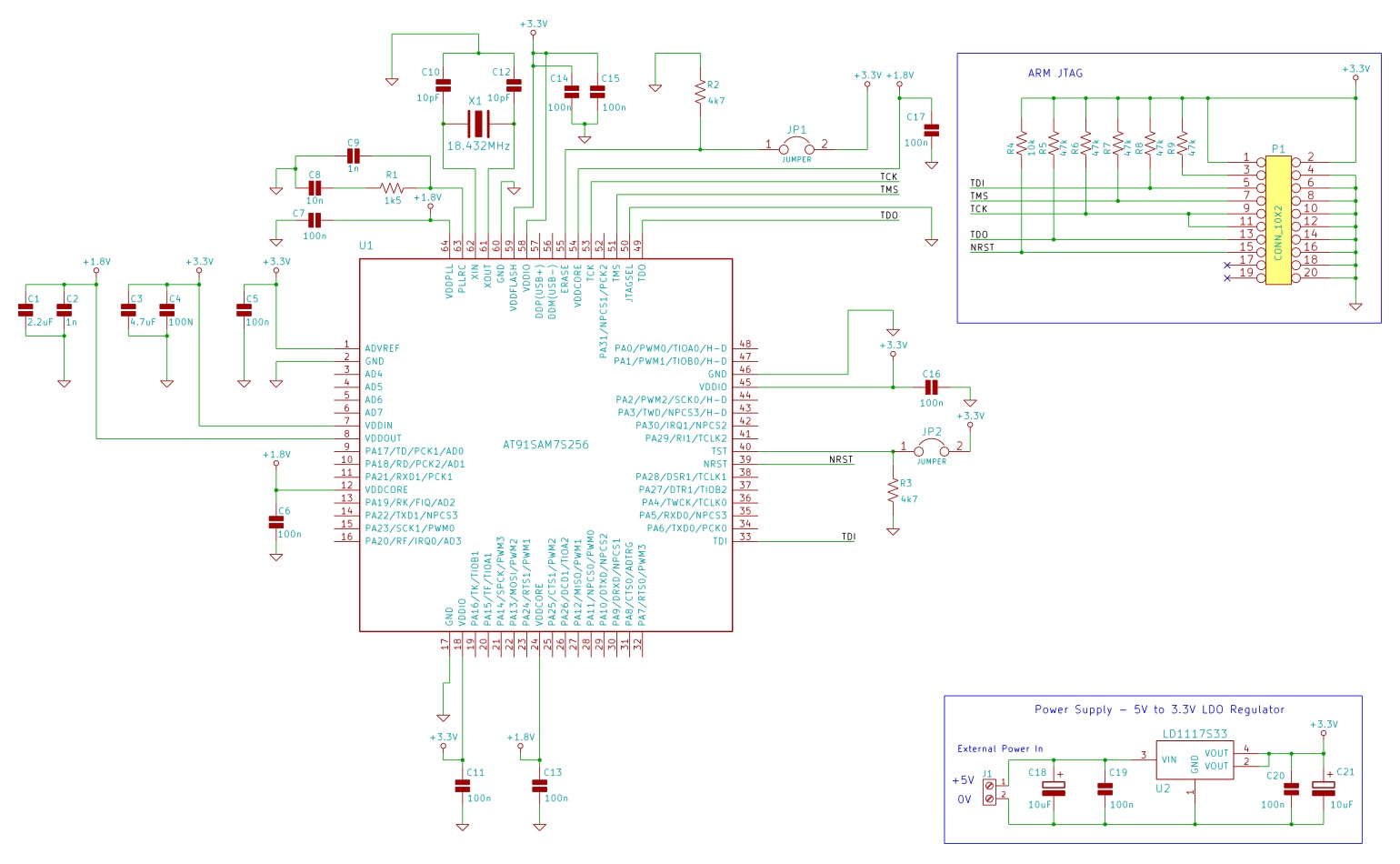
The minimum number of supporting components required to build a circuit using AT91SAM7S microcontrollers. This example uses the AT91SAM7S256 ARM7 microcontroller. To construct a circuit utilizing the AT91SAM7S256 ARM7 microcontroller, a minimal set of supporting components is essential to ensure...