
Stereo Preamplifier with adjustment tone circuit

The described preamplifier circuit leverages the Motorola TCA5550 operational amplifier, which is designed for audio applications due to its low noise characteristics and high gain. The TCA5550 is a dual op-amp, allowing for multiple signal processing paths within a single package. This feature is particularly beneficial for audio applications where multiple adjustments, such as volume, balance, treble, and bass, are required.
To construct the circuit, a basic schematic would include the TCA5550 connected in a non-inverting configuration to provide gain to the audio signal. The input from the audio source connects to the non-inverting input of the first op-amp, while the output is fed back through a resistor network that sets the gain. The output from this stage can then be routed to the second op-amp for further processing, where additional potentiometers for balance, treble, and bass are integrated.
The use of linear potentiometers for adjustments allows for smooth and intuitive control over the audio output. Each potentiometer should be connected to the appropriate input of the op-amp, with careful consideration given to the layout of the circuit. Keeping the potentiometers close to the TCA5550 minimizes the potential for noise interference, which is crucial in audio applications where clarity is paramount.
Power supply considerations for the circuit are also essential. The TCA5550 typically operates within a specified voltage range, and adequate decoupling capacitors should be placed near the power supply pins to ensure stable operation. The circuit does not demand high current, making it suitable for battery-powered applications or low-power designs.
Overall, this preamplifier circuit design is an efficient and effective solution for basic audio signal amplification and processing, suitable for various applications where simplicity and performance are required.Many times we needed to use a simple circuit of preamplifier, with few components and facility of made. This circuit use a opamp. the Motorola, TCA5550, that contains a double amplifier, as outputs for the adjust of volume, balance, treble and bass.
These adjustment of all parameters become from a line monophonic linear potesometers, increasing by far the facility of manufacture. The placement these potesometers should become as much as possible, more near in IC1, so that is minimised the noise.
The circuit does not require big current in order to it work.. 🔗 External reference
Related Circuits
This circuit functions to monitor the duration of occupancy in a toilet, activating an alert if the time spent exceeds a predefined limit. The components involved include a resistor, integrated circuit (IC), capacitor, and transistor. The occupancy monitoring circuit is...
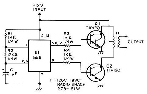
This low-power 25-watt power inverter circuit utilizes only nine electronic components. The inverter converts a DC input voltage ranging from 10V to 16V into a 60Hz, 115V square-wave power output, capable of powering AC electronic devices up to approximately...
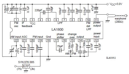
This portable AM/FM radio circuit is designed using the LA1800 integrated circuit (IC) along with several external components. The LA1800, manufactured by Sanyo Semiconductors, requires only a few additional components for its operation. The output signal is directed to...
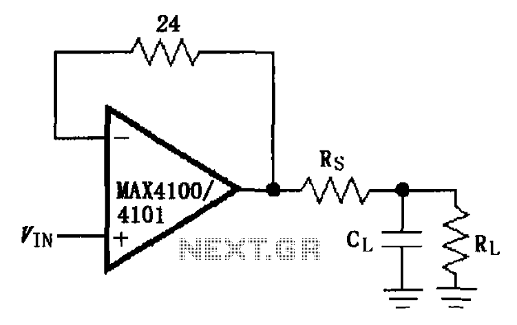
The MAX4100/4101 operational amplifiers utilize a capacitive load drive circuit with an isolation resistor Rs. The MAX4100 and MAX4101 can handle maximum capacitive loads of 5pF and 20pF, respectively, but are susceptible to overshoot and ringing oscillations. To mitigate...
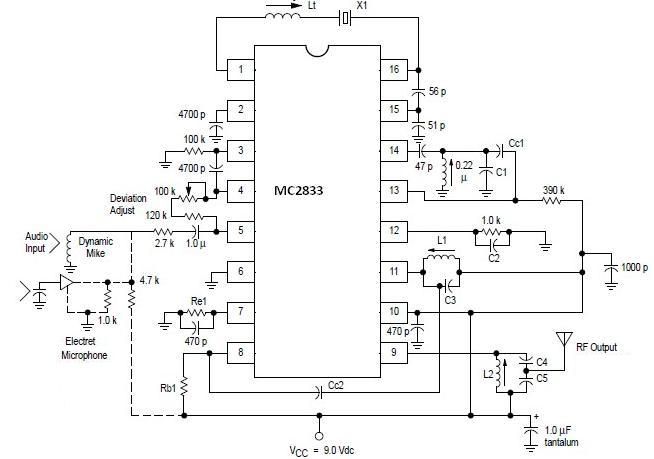
A simple FM transmitter circuit can be designed using the MC2833 integrated circuit, which is intended for cordless telephones and FM communication equipment. It features a microphone amplifier, a voltage-controlled oscillator, and two auxiliary transistors. The final output frequency...
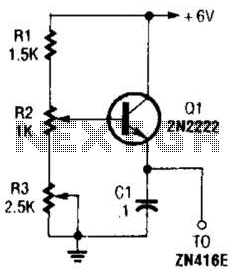
This regulator can be used with a +6-V source to supply the ZN416E low-voltage TRF radio receiver IC with the necessary +1.5 V. R3 sets the output voltage. The circuit utilizes a voltage regulator designed to convert a +6 V...