
app note high voltage led applications

The MLX10803 is a versatile high-voltage LED driver IC designed for efficient operation in various lighting applications. It integrates features that allow for precise control of the current flowing through high-power LEDs, ensuring optimal performance and longevity. The architecture typically includes a PWM dimming capability, which enables brightness control without significant losses in efficiency.
For implementation, the circuit should incorporate a high-voltage power supply, suitable capacitors to filter and stabilize the input voltage, and inductors designed to handle the expected currents without saturating. The layout of the PCB is critical; it must adhere to high-voltage design rules to prevent arcing and ensure safety. This includes adequate spacing between traces, use of high-voltage rated components, and proper grounding practices to minimize noise and enhance reliability.
Thermal management is another crucial aspect. Since high-power LEDs can generate significant heat, the design must account for heat dissipation through the use of heat sinks or thermal vias, ensuring that the junction temperature of the LEDs remains within safe operating limits.
To mitigate electromagnetic interference (EMI), careful routing of signal traces and the inclusion of filtering components may be necessary. Ferrite beads and capacitors can be employed to suppress high-frequency noise generated by the switching action of the driver.
In summary, while the MLX10803 provides a robust solution for driving high-power LEDs, it necessitates a thorough understanding of high-voltage design principles, component selection, and PCB layout techniques to ensure a successful and safe implementation.The applications described in this document are applications for driving high power LED diodes. The described circuits can be applied on other applications with similar circumstances as well, in case they fall within the specifications of the MLX10803. This is a conceptual description and in some case no component values are given. The application s described in this document have in most cases been implemented. Demonstration systems and components are available at Melexis. Please contact our closest sales office or representative to learn more It is not a trivial task to design for high voltage, great care must to be taken in respect for the high voltages involved. The examples given in this document have to be carefully designed and fabricated. Slight errors can have devastating results. These examples are not recommended for the inexperienced or untrained lay people, it is intended for electrical and electronic engineers with relevant training and experience designing and building high voltage circuits.
The circuit board has to be design according to high voltage rules. Depending on the users The circuits described in this document have a very good efficiency, converting efficiencies up to 98-99% is to be expected! This makes the circuit design fairly simple in respect of thermal handling. Please remember that if you design lamps with up to 100 watt and more, even 1% loss generates 1 watt, and more of heat.
Every kind of active current regulation generates ripple on the regulated output, this ripple can generate electromagnetic radiation (EMR), resulting in electromagnetic coupling to the surrounding electronic (EMC). The MLX10803 and the applications described in this document are designed to minimize EMR. Additional care has to be taken when designing the circuit board and the physical application. Melexis makes no claims about the suitability of any of these circuits for EMI/EMC and EMR compliance against international regulations.
Compliance testing is recommended and it will fall to the user to conduct such testing prior to sale in specific countries and markets. High volt design is more demanding than making low voltage applications using MLX10803. We strongly recommend using the following presented tools when making high volt applications. Use these tools for your own safety, before you connect your LED application to the 110/220 V net. Find this program on the Melexis web site at, . Download the coil_calc_(x). zip file and use the Microsoft Excel spreadsheet included. The spreadsheet is self instructive. Play with it and get a feeling about the relation ship between coils, currents and sense values. The real mathematics behind the MLX10803 function is complicated, this sheet is a simplification. The tool gives only rough values, but it gives an impression what component sizes and settings are needed.
After finding out coil, reference resistors and sense resistor value, as well as mono flop time, oscillator resistor value and sense voltage settings with this tool, it is time to apply the component values to the MLX10803 LED driver circuit and try out the values in an application. The LED supply can be separated from the circuit supply (VS/PWM) by removing the jumper for that on the EVB10803.
See the manual for EVB10803 for instructions. When the supply to the LED is separated from the VS/PWM then the supply voltage to the LED is limited by the switching N-FET transistor parameters and the fly back diode. Please use this option with great care, and check carefully what type of transistor and fly back diode your EVB10803 is equipped with before applying any higher voltage than 32V.
🔗 External reference
Related Circuits
The provided description pertains to a unique low voltage variant of an audio preamp. The emitter voltage of T1 is biased close to half the supply voltage, which is 1.5V. This biasing allows for the maximum output voltage swing. The...
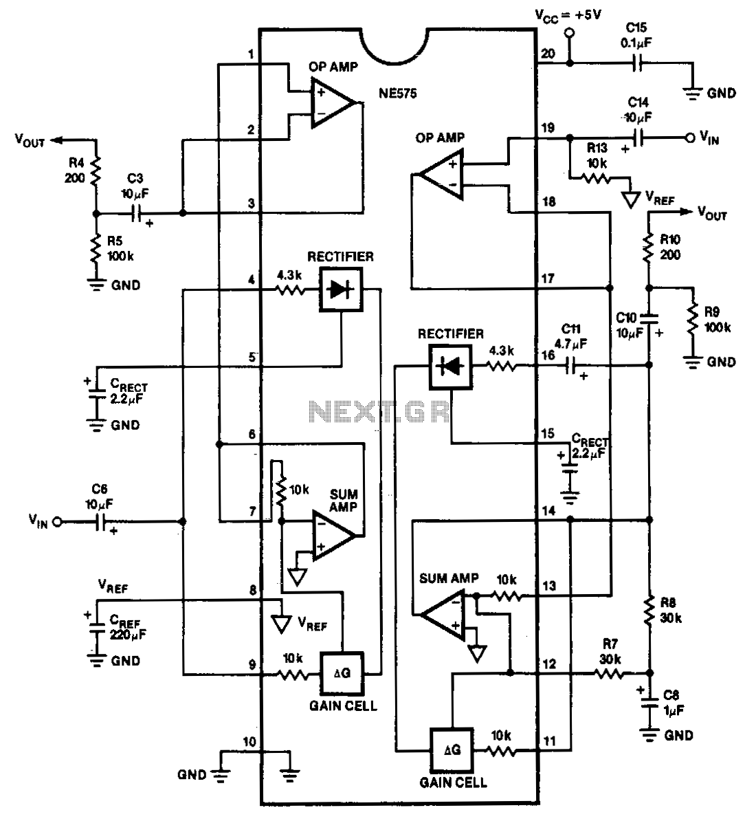
The NE575 is a dual-gain control circuit designed for low voltage applications. Channel 1 acts as an expander, while Channel 2 can be configured for expander, compressor, or automatic level controller (ALC) applications. The NE575 dual-gain control circuit is specifically...
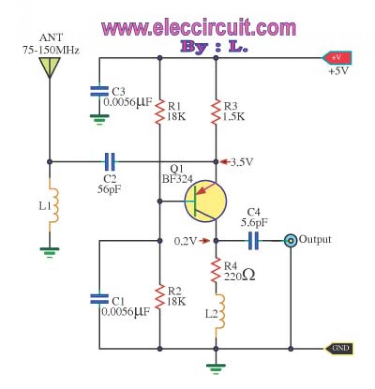
This is a wideband high-frequency amplifier circuit designed for a frequency range between 75-150 MHz. It utilizes a PNP transistor amplifier to enhance signal strength before it reaches the receiver of devices such as phones, FM radios, or amateur...
In the circuit below, 60 individual LEDs are used to indicate the minutes of a clock and 12 LEDs indicate hours. The power supply and time base circuitry is the same as described in the 28 LED clock circuit...
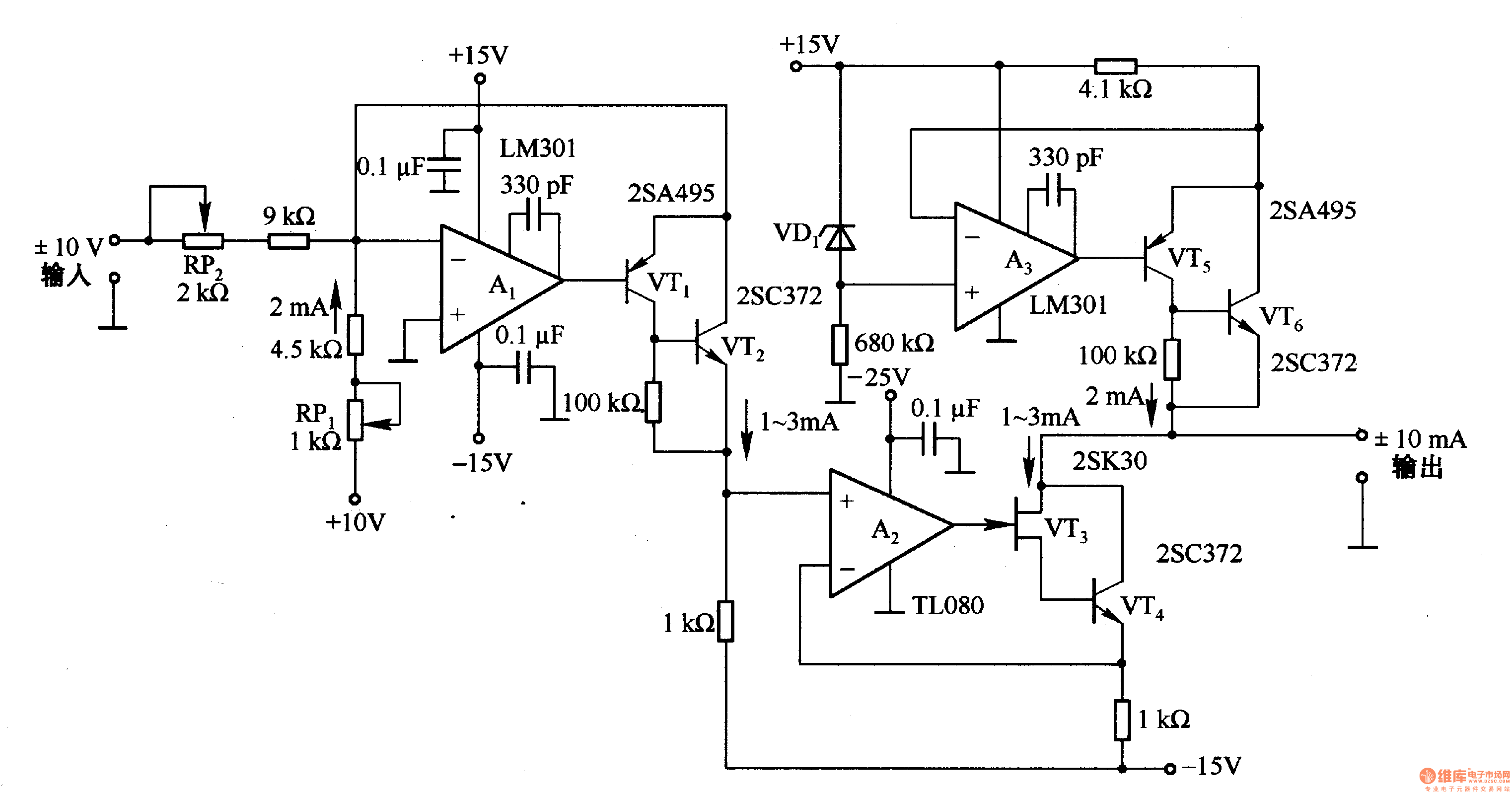
This circuit is designed for voltage-to-current conversion, specifically transforming a ±10V input voltage into a ±1mA output current. The conversion process is facilitated by operational amplifier A1 and transistors VT1 and VT2, which are responsible for altering the current...
It is often challenging to measure the current in the positive lead of a power supply, such as a battery charger. Fortunately, specialized integrated circuits (ICs) have been developed for this purpose in recent years, including the Burr-Brown INA138...