
Voltage/current conversion circuit composed of LM301

The voltage-to-current conversion circuit operates by utilizing an operational amplifier (A1) configured in a feedback loop to maintain a precise output current that corresponds to the input voltage. The transistors (VT1 and VT2) function as switches that control the direction of the output current, allowing for both positive and negative current outputs depending on the input voltage polarity.
The circuit's design includes a biasing mechanism that ensures a constant 2mA current flows when the input voltage is at 0V. This feature is essential for applications that require a baseline current level for proper operation. The inclusion of a constant current source at the output further stabilizes the output current, ensuring that it remains at 2mA regardless of variations in load resistance.
In practical applications, this circuit can be utilized in sensor interfacing, where voltage signals from sensors need to be converted into current signals for further processing or transmission. The precision of the operational amplifier and the current control provided by the transistors make this circuit suitable for high-performance requirements in industrial and scientific instrumentation. Overall, the design is robust and reliable, providing a straightforward solution for voltage-to-current conversion tasks.It is the conversion circuit, which can transform ±10V voltage into ±lmA, and the input voltage is changed into current by the A1 and VTl, VT2, and it is used to change the current direction. The input end is added 2mA bias current, when the input voltage is OV, there is 2mA current flowing; the output termination is added 2mA constant current source circu..
🔗 External reference
Related Circuits
Electrical signals travel along the neurons in the brain and body, continuously transmitting information throughout the complex system. Without these signals, the body would function like a plant, with different parts unaware of each other's conditions, making animal life...
This mini audio amplifier will test the audio stages in amplifiers such as the front end of FM bugs. You can also use it on lots of our other projects as well as the output stages of radios. It...
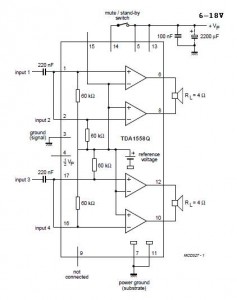
A 2x22 W car audio amplifier circuit utilizes the TDA1558, a monolithic integrated class-B output power amplifier that includes four 11 W single-ended amplifiers or two 22 W bridge-tied load (BTL) amplifiers. The TDA1558 is designed to drive speakers in...
Solar panels operate at optimal parameters when positioned at the ideal angle to the sun. This alignment is achieved by rotating the solar panels to track the sun's movement. A DIY solar tracker system can be constructed using an...
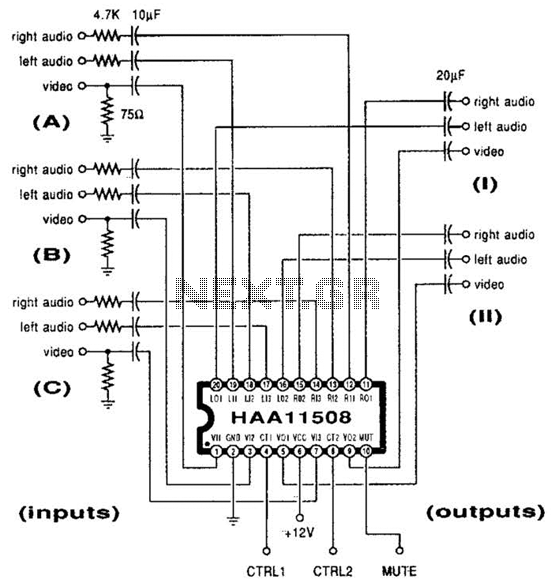
This channel selector selects video and stereo audio from any one of three different sources. The circuit should be constructed on a PC board with plenty of ground plane to minimize noise. The channel selector circuit is designed to facilitate...

Converting a 1958 Buick to electric wipers with delay and automatic "wipe on wash" functionality while integrating the new electrical components with the original non-electric wiper controls to maintain a consistent driver experience. The conversion process is ongoing, and...