
Arduino Analog WriteMega

In this LED circuit design, the anodes of 12 LEDs are connected to digital pins 2 through 13 of a microcontroller, such as an Arduino. Each anode connects through a 220-ohm resistor, which serves to limit the current flowing through the LED, preventing damage and ensuring proper operation. The cathodes of the LEDs are connected directly to the ground, completing the circuit.
The sequential illumination of the LEDs is controlled by the microcontroller's programming. The code will iterate through each digital pin connected to the LEDs, turning them on one at a time. This requires a loop structure that includes a delay to allow each LED to be visibly illuminated before moving to the next.
In the code, the first step involves setting the digital pins to OUTPUT mode to prepare them for controlling the LEDs. The next step is to set a specific pin HIGH to turn on the corresponding LED while ensuring all other pins are set LOW to turn off the remaining LEDs. After the LED is activated, a delay function is typically employed to maintain the LED's brightness for a specified duration. Once the delay period has elapsed, the code will proceed to the next pin in the sequence, repeating the process until all LEDs have been illuminated.
This design effectively demonstrates basic principles of digital electronics, including the use of resistors for current limiting, the control of output pins via programming, and the fundamental operation of LEDs in a circuit. The implementation can be expanded by incorporating additional features such as varying brightness levels using PWM (Pulse Width Modulation) or creating different lighting patterns for more complex visual effects.Connect the longer, positive legs of (anodes) 12 LEDs to digital pins 2-13 through 220 ohm current limiting resistors. Connect the shorter, negative legs (cathodes) to ground. moves through each of the LEDS one by one, from the lowest pin to the highest. Before this loop is allowed to move from one pin to the next, two things must be accomplished. First, you brighten the individual LED through these lines of code: 🔗 External reference
Related Circuits
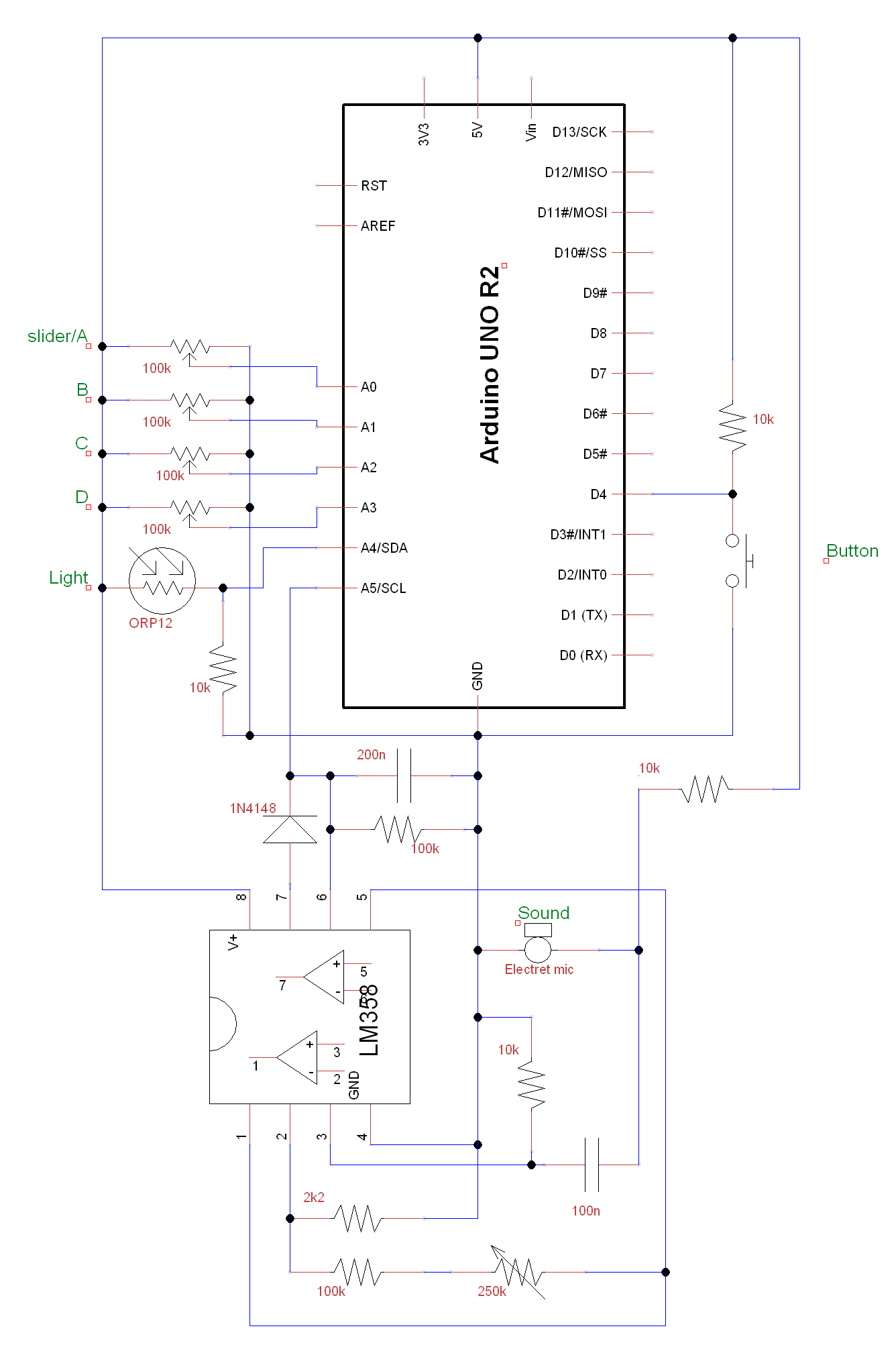
A circuit and Arduino code are designed to emulate a ScratchBoard approximately. The setup includes sound, light, a button, and four sliders, but it is not a direct replacement. It is important to change the COM ports in the...
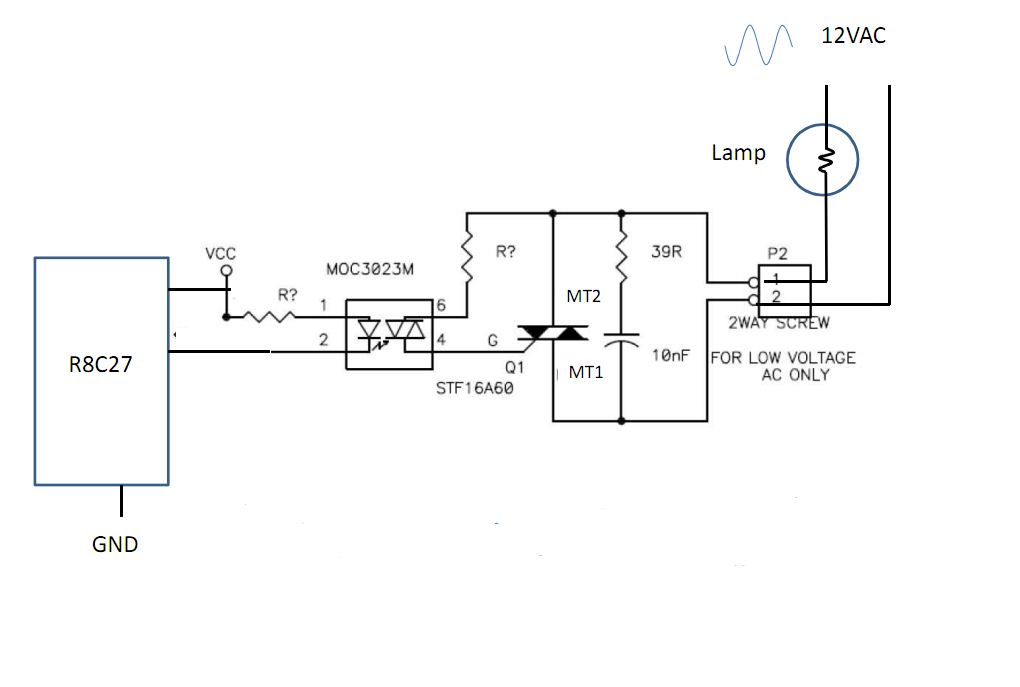
Control 30 incandescent light bulbs with an Arduino Uno on three channels (10 bulbs per channel in parallel). Previous experience involved using an Arduino to control red, green, and blue LEDs with a simple schematic that included three transistors....
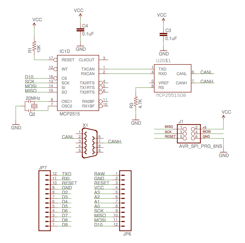
The implementation of the Controller Area Network (CAN) for aircraft applications is referred to as CAN-FIX, which is part of the MakerPlane Open Source Airplane project. This project aims to create an Arduino shield that facilitates communication over the...
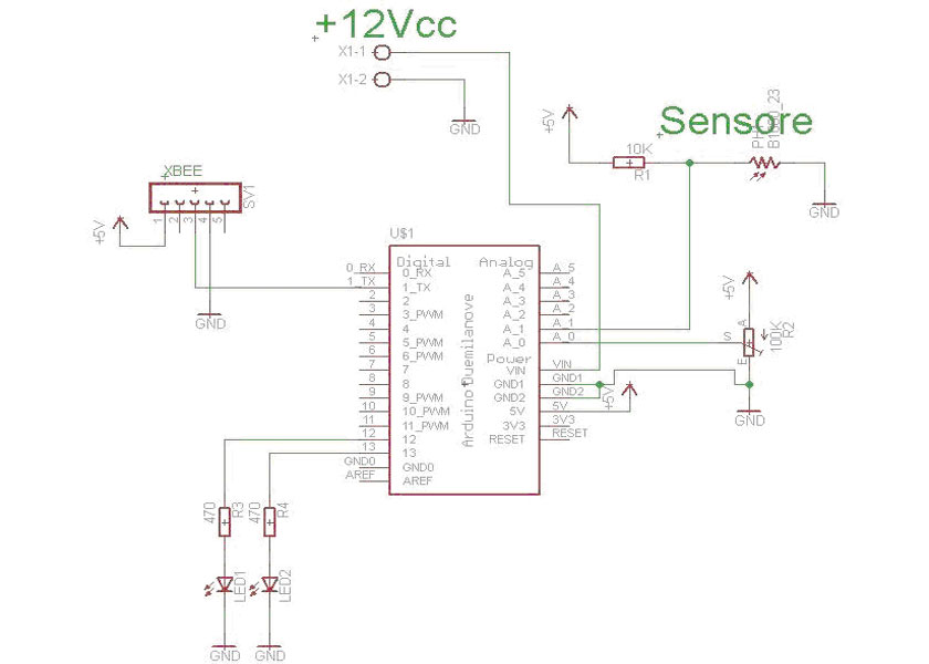
The system consists of two components: an Arduino board that detects LED pulses and transmits the data via an XBee module, and a PC that receives the data through a USB/XBee module and processes it using LabVIEW, allowing for...
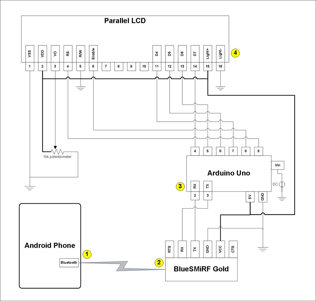
This project involves a modification of the Google Android sample app known as Bluetooth Chat, allowing users to type a message in the Android app and display that same message on an LCD connected to an Arduino Uno. The...

A simple circuit utilizing an LM311 as a level detector and a CMOS analog gate for capacitor discharge is presented. A notable feature of this counter type is the ease of changing the count, which only requires adjusting the...