
ScratchBoard Emulator using Arduino Uno

The described circuit consists of an Arduino microcontroller interfacing with various input and output components to simulate a ScratchBoard environment. The primary components include sound output devices, LED lights, a push-button switch, and four analog sliders, each of which serves as an input device. The sound output can be achieved through a piezo buzzer or a speaker connected to a PWM-capable pin on the Arduino, allowing for sound generation based on user interaction.
The light component typically involves one or more LEDs connected to digital output pins, which can be toggled or dimmed based on the state of the sliders or button presses. The button is connected to a digital input pin configured with an internal pull-up resistor, ensuring reliable detection of button presses.
The four sliders can be implemented using potentiometers connected to the analog input pins of the Arduino. Each slider's position can be read as a voltage value, which the Arduino converts to a corresponding digital value ranging from 0 to 1023. These values can then be transmitted to the Scratch environment via serial communication, allowing Scratch to respond to user inputs dynamically.
To ensure smooth operation, proper configuration of the COM ports in both the Arduino IDE and Scratch is crucial. Users must ensure that the selected COM port for the Arduino does not conflict with the one used by Scratch. The process of setting up the sensor values within Scratch involves right-clicking on the sensor value block to access the watcher feature, which allows for real-time monitoring of the input values. Following this, users can configure the COM port settings to establish a successful connection between the Arduino and Scratch.
This project serves as an educational tool, demonstrating the integration of hardware and software through Arduino programming and Scratch coding, thereby providing an interactive learning experience. The unique combination of components allows for experimentation with sound, light, and user input, making it an engaging project for both beginners and experienced users in the field of electronics and programming.A circuit and arduino code to approximately emulate a ScratchBoard ; there is sound, light, a button and four sliders but it isn`t a drop-in replacement. remember to change the COM ports in the Arduino IDE and in Scratch so that they are not competing (if the Arduino is on COM3 then only one of the IDE or Scratch can use COM3 at a given ti
me) configuring things in Scratch is a bit cryptic: you need to right-click on the sensor value block to show the watcher then right-click on that to set the COM port. This was written by Adam. Posted on Monday, February 27, 2012, at 11:35 pm. Filed under Arduino, Microcontrollers. Bookmark the permalink. Follow comments here with the RSS feed. Post a comment or leave a trackback. 🔗 External reference
Related Circuits

This Arduino-based project involves constructing a lamp with various light displays, including a color sequencer, dimming light, color chaser, and firelight, all controlled by a touch bar on the circuit board. The design adopts a minimalist approach, incorporating only...
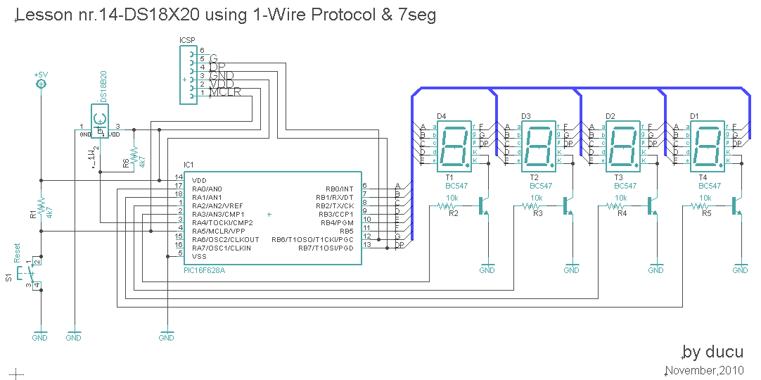
In this lesson, a digital temperature meter will be constructed using the DS18B20 temperature sensor. The connection between the temperature sensor and the microcontroller will utilize a single wire, which is a significant advantage of this sensor model. The...
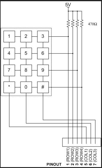
If the number 8 is pressed, it will affect the wire ROW3 and COL2. This allows the microcontroller to determine which key was pressed using only 7 wires from the keypad. The described circuit involves a matrix keypad configuration, which...

The circuit presented here is a powerful AM transmitter utilizing a ceramic resonator/filter operating at 3.587 MHz. This circuit primarily relies on a transistor for its core functionality. It is possible to use resonators/filters of other frequencies, such as...

This circuit is a diagram of a mini amplifier. The amplifier circuit has a power output of 10 watts and is well-suited for car audio applications. It utilizes the TDA2009A integrated circuit as the power amplifier. To prevent excessive...

The circuit diagram represents an ultra-sensitive intruder alarm. A shadow from an intruder passing nearby is sufficient to trigger the alarm. The operational amplifier IC2 (uA 741) is configured as a sensitive comparator, with its set point determined by...