
Arduino Barometric Pressure WebServer

The circuit design incorporates an SCP1000 Barometric Pressure sensor interfaced with an Arduino microcontroller through the SPI protocol. The SPI interface utilizes four essential connections: MOSI, MISO, SCK, and CSB. The MOSI line is responsible for transmitting data from the Arduino to the sensor, while the MISO line carries data from the sensor back to the Arduino. The SCK line serves as the clock signal to synchronize the data transfer, and the CSB line is used to select the sensor for communication.
In this setup, the Arduino acts as a master device, initiating communication with the SCP1000 sensor. The DRDY pin is crucial as it indicates when the sensor has new data available for reading. The Arduino monitors this pin to determine when to request data, ensuring accurate and timely readings of temperature and barometric pressure.
The Ethernet Shield facilitates network connectivity, allowing the Arduino to function as a web server. By utilizing the Ethernet library, the Arduino can handle incoming HTTP requests and serve HTML content that displays the sensor data. This capability transforms the Arduino into a simple web server, enabling remote access to sensor readings via a web browser.
To ensure proper operation, it is essential to configure the network settings within the Arduino sketch. This involves specifying the IP address, subnet mask, and gateway to match the local network environment. Once configured, the Arduino can communicate over the network, providing real-time access to the barometric pressure and temperature data collected from the SCP1000 sensor.This example shows how to use SPI communications to read data from a SCP1000 Barometric Pressure sensor, and how to then post that data to the web by using your Arduino/Ethernet Shield combo as a simple web server. Using the Ethernet library, your device will be able to answer HTTP requests by responding with just enough HTML for a browser to dis
play the temperature and barometric pressure values outputted by your sensor. After completing your circuit and uploading the example code below, simply navigate to your Ethernet shield`s IP address, in a browser, to see this information. Your Barometric Pressure sensor will be attached to pins 6, 7, and 11 - 13 of your Arduino/Ethernet shield combo, and powered via your device`s 3.
3 volt output. Connect the DRDY (Data Ready) pin on your sensor to digital pin 6 on your combo, and the CSB pin (Chip Select) to digital pin 7. Your sensor`s MOSI (Master Out Slave In) pin should then be connected to digital pin 11, and it`s counterpart MISO (Master In Slave Out) to digital pin 12.
Finally, connect the SCK pin, the SPI clock input on your sensor, to digital pin 13 on your device, and make sure that the two share a common ground. After wiring your sensor, your shield should be connected to a network with an ethernet cable. You will need to change the network settings in the program to correspond to your network. 🔗 External reference
Related Circuits

The Arduino Uno schematic diagram is available for viewing. The Arduino Uno is a microcontroller board that utilizes the ATmega328 chip. It features 14 digital input/output pins, of which 6 can be used as PWM outputs, and 6 analog...
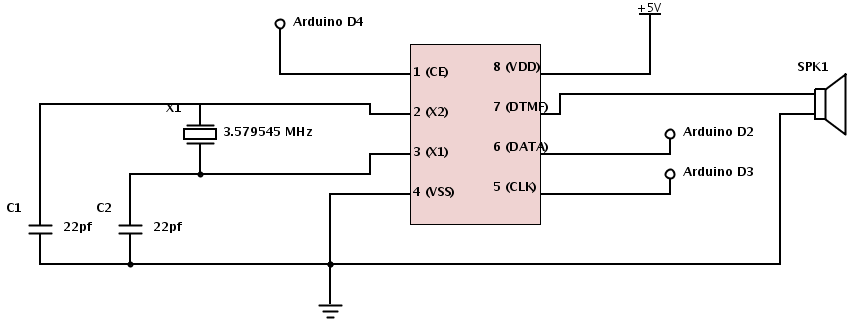
The project involves teaching an Arduino to generate DTMF (Dual-Tone Multi-Frequency) tones using the HT9000A DTMF chip. These tones are the familiar "touch tones" used in telephone systems. The output volume from the chip is low, suggesting the need...

In this series, a diverse exploration of how Arduino interacts with various real-world devices has been presented, from servo motors to ultrasonic range finders, TVs to humidity sensors. The focus now shifts to generating sound using Arduino. The project...
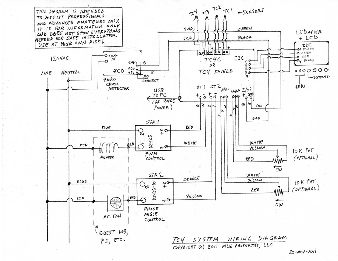
This is a complete standalone system compatible with Arduino Uno, which will be fully assembled, tested, and programmed prior to shipping. Users can select from various TC4 applications to be pre-programmed into the board. For those who wish to...
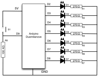
Electronic devices require precision. When a task is performed multiple times, the outcome is consistently the same. However, there are instances where random results are desirable, such as in gaming applications. This project demonstrates how to create a lottery...
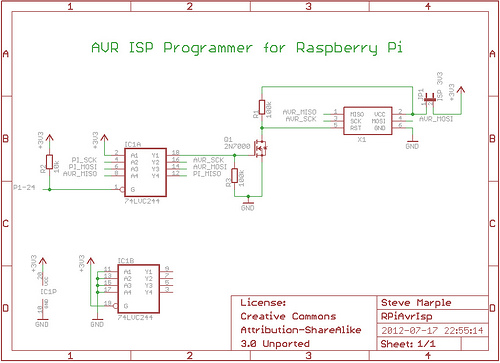
As a fully-featured Linux computer, many external programmers can be used with the Raspberry Pi to program the Atmel AVR range of microprocessors. It is also possible to utilize the general-purpose input/output lines (GPIOs) found on the Raspberry Pi...