
Arduino UNO

The Arduino Uno is an essential platform for electronics prototyping and development. The ATmega328 microcontroller at its core operates at a clock speed of 16 MHz and provides a robust environment for executing various programs. The board is equipped with 14 digital I/O pins, allowing for versatile interfacing with other electronic components. Among these, 6 pins are capable of Pulse Width Modulation (PWM), which is particularly useful for applications requiring variable signal outputs, such as controlling the brightness of LEDs or the speed of motors.
Additionally, the Arduino Uno contains 6 analog input pins that can read varying voltage levels from sensors, enabling the board to interpret real-world signals. The board is powered via a USB connection or an external power supply, which can provide voltages between 7 to 12 volts. The onboard voltage regulator ensures that the microcontroller and connected components receive a stable 5V supply.
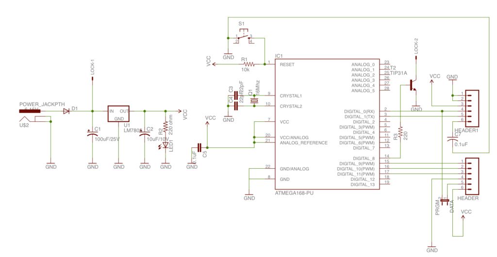
The schematic diagram of the Arduino Uno includes details about the power supply, pin configurations, and connections to critical components such as the crystal oscillator, reset button, and the USB interface. Understanding the schematic is crucial for anyone looking to modify the board or integrate it into larger systems, as it provides insight into the electrical pathways and component interactions. The simplicity and versatility of the Arduino Uno make it a favored choice among hobbyists and professionals alike for developing and testing electronic projects.Here the Arduino UNO schematic diagram (click to enlarge): About Arduino UNO: The Arduino Uno is really a microcontroller board based on the ATmega328. It has 14 digital input/output pins (of which 6 may be employed as PWM outputs), 6 analo.. 🔗 External reference
Related Circuits
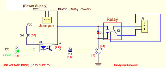
Control a relay from an Arduino-compatible board. When attempting to activate the relay from the Arduino, it takes at least a second to close, and sometimes it does not close at all. Digital pin 2 of the Arduino is...
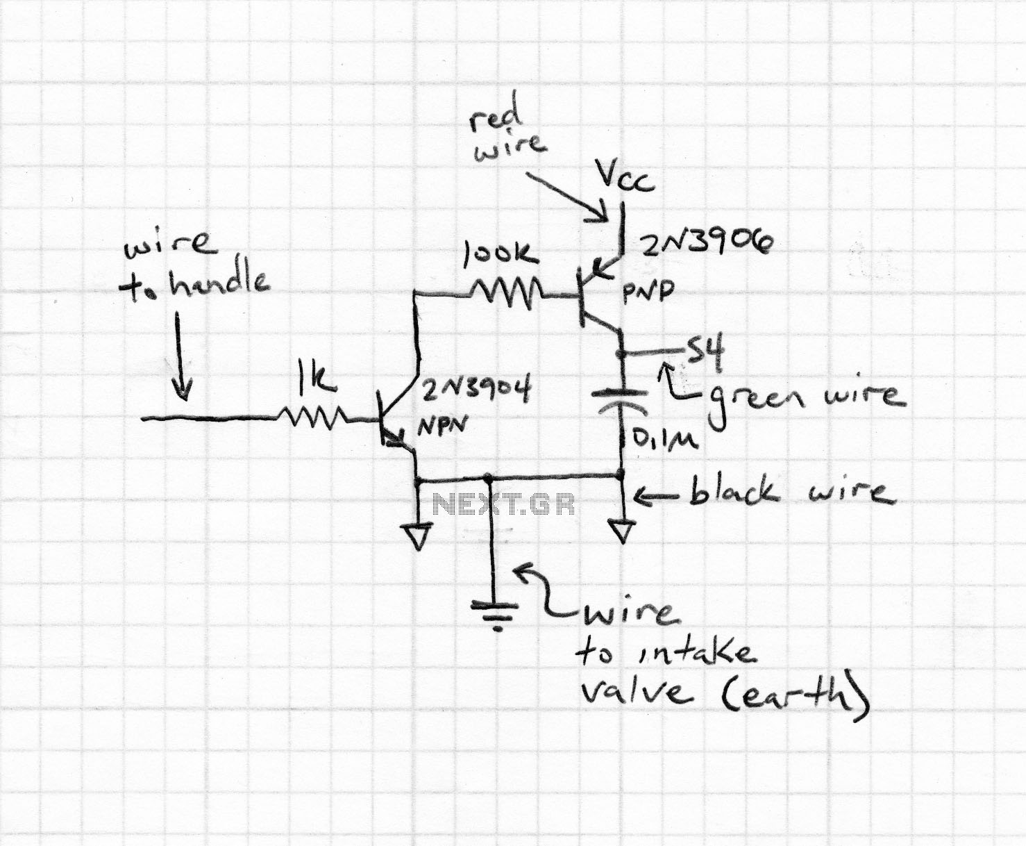
This section of code outlines the main sequence of operation for the sequencer. A for loop is utilized to determine which step the sequencer is operating in. Within this loop, an address is generated using the assignByteToPins() function, which...
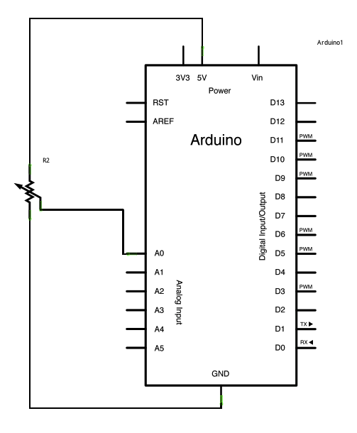
A potentiometer is a simple knob that provides variable resistance, which can be read into the Arduino board as an analog value. In this example, a potentiometer is connected to one of the Arduino's analog inputs to control the...
The initial step in constructing an RFID door lock using a basic Arduino involves breadboarding a fundamental working Arduino setup. Most Arduino boards equipped with pre-flashed ATMega 168 chips come with a default blink program installed. A LED should...
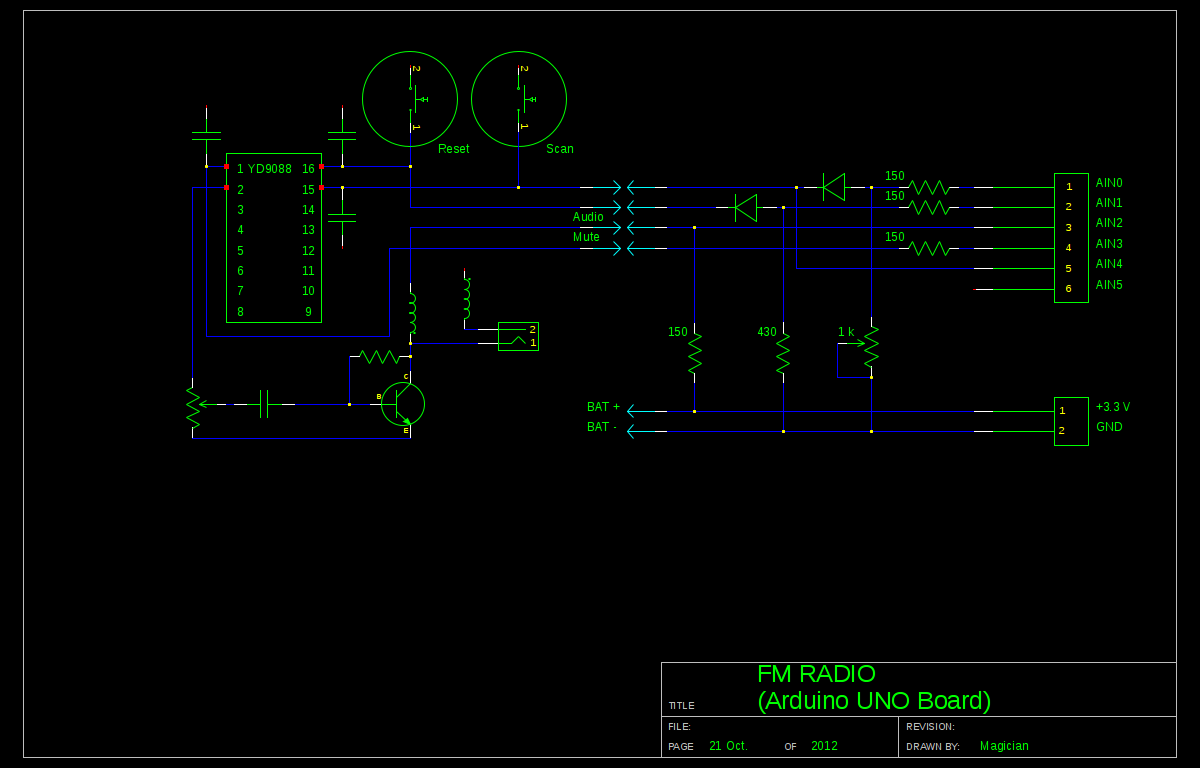
A local convenience store (Dollarama in Montreal, Canada) offers an appealing FM radio for just $3. The idea of interfacing this radio with an Arduino presents a fun challenge. Although the primary goal is not to create a radio,...
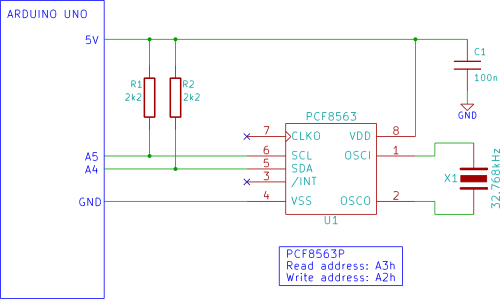
The Arduino displays the time and date on an optional LCD and in the Arduino IDE serial monitor window. A PCF8563 real-time clock (RTC) integrated circuit (IC) is utilized to generate the time and date. The time and date...