
Arduino Day-Night Controller

The circuit operates through two primary sections: light sensing and power switching, demonstrating the integration of an Arduino microcontroller for automation. The light sensing section employs a photo-resistor (R4), which functions as part of a voltage divider configuration with resistor R2. The resistance of the photo-resistor varies inversely with the intensity of light it receives, thus altering the voltage output from the divider. This voltage, ranging from 0 to 5 volts, is supplied by the Arduino board through connection J4. The Arduino's analog input pin, designated as "Analog Pin 0" and connected via J3, reads this voltage using the `analogRead` function. This function converts the analog voltage to a digital value between 0 and 1023, thereby allowing the Arduino to detect minute changes in light levels with a resolution of approximately 0.0048 volts.
The power switching section utilizes an NPN transistor (Q1) to control the operation of connected devices based on the light sensing input. The transistor acts as a switch, which is activated by a digital signal from the Arduino through Digital Pin 3, connected via J2. When the light level falls below a predetermined threshold, the Arduino sends a signal to the transistor, allowing current to flow from the supply voltage at J1 to the output at J5. This output can be connected to low voltage devices such as LEDs or other light sources, enabling them to turn on automatically in low-light conditions.
The circuit design includes considerations for PCB layout, with options for a ground plane to enhance performance and minimize noise, providing flexibility based on user preference. The overall design leverages the capabilities of the Arduino to simplify the circuit's complexity, showcasing the advantages of microcontroller-based solutions in electronic projects.The Circuit is composed of two sections, the light sensing and the power switching. The light sensing part consists of a photo-resistor R4, connected like a voltage divider to R2. Since the resistance of the photo-resistor changes depending on the amount of light that is shining on it, the voltage divider's voltage ratio changes depending on the amount of light present. The voltage going through this part of the circuit is 5 volts dc, supplied from the Arduino board to J4 of the circuit.
So the voltage divider is dividing the voltage between the maximum 5 volts, to the minimum 0 volts. The Arduino senses this voltage on its "Analog Pin 0" that connects to J3 on the circuit. This is called "analogRead," it divides the 0 to 5 volts by 1024 (10 bits, or 2^10) so it can sense a change in voltage as small as .0048 of a volt. This is an Arduino controlled light sensing switching unit. Its main use is to control solar lights to turn on when it is dark outside, but it can work in many more applications. The power switching section of the circuit is quite simple; it uses a NPN switching transistor Q1, that is digitally controlled by the Arduino board from 'Digital Pin 3' connected to the circuit through J2.
It switches the negative leg of the supply voltage from J1. J5 is where a low voltage light or anything you want turned on and off is connected. This guide will walk you through every aspect of the building process. Prior knowledge of the Arduino unit is not necessary since the code and schematic have been supplied for you. This project would be fairly complex to build without an Arduino; it is a good example of how a microcontroller can make a circuit far less complex, with less hardware trial and error.
There is no R3 on the schematic, my apology I labeled the photo-resistor R4 on accident, sorry. I included two different PCB bottom copper designs, one has a ground plane and the other does not. Use whichever you prefer. I won't go into the parts of the Arduino, mainly because it is already a well-documented unit. The picture at the top should make it fairly obvious to see how it is connected. 🔗 External reference
Related Circuits
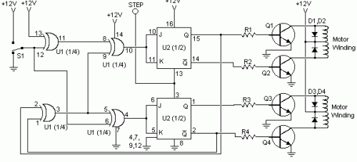
This circuit is constructed using standard components and can be easily adapted for computer control. By utilizing inexpensive surplus transistors and a stepper motor, the overall cost of the circuit can be maintained at under $10. The described circuit is a...
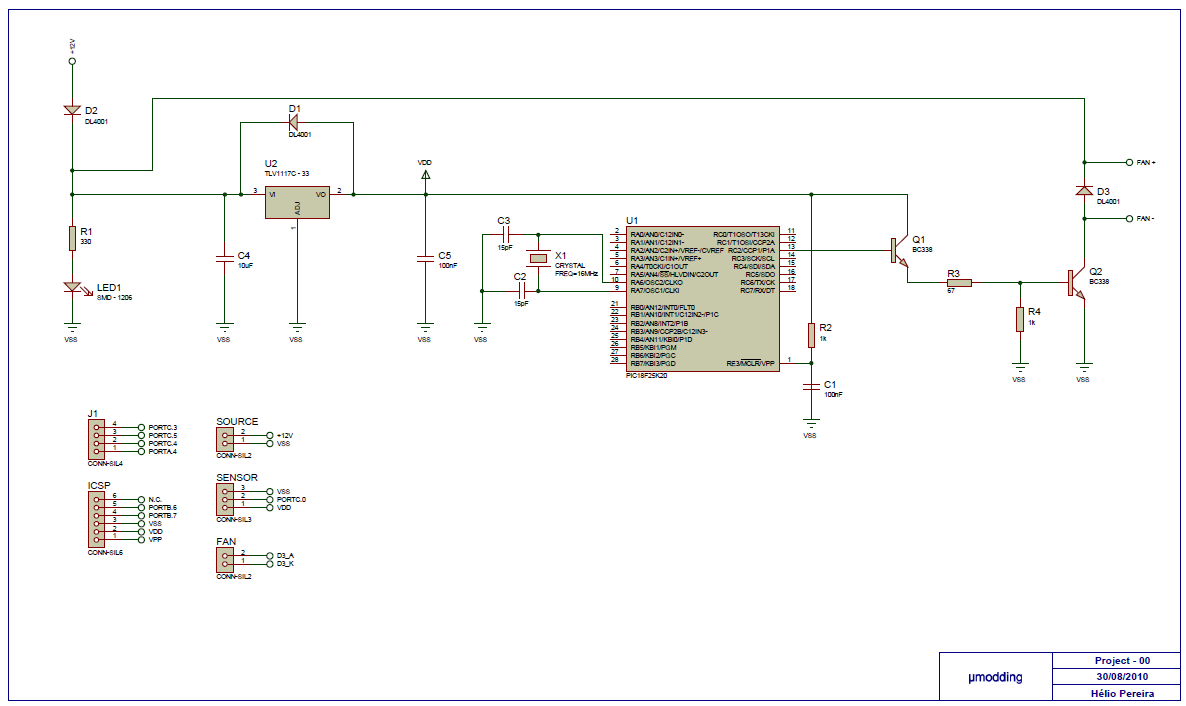
This project is based on a PIC18F25K20, with the purpose of controlling a fan with PWM (Pulse Width Modulation). It offers variable speed control, low acoustic noise, reliability, long lifetime, low power consumption, and protection features. The MCU gets...

The schematic for the board is illustrated below. The three primary components of the board include (1) the power input and voltage regulation, (2) the L297 input and outputs, and (3) the L298 stepper motor control circuit. The motor...
Voltage regulator ICs (78xx series) deliver a stable output voltage despite a fluctuating input supply when the common terminal is grounded. Any voltage above zero volts (ground) connected to the common terminal is added to the output voltage, meaning...
If you are interested in working with Arduino, you may have considered creating your own Arduino board. Creating a custom Arduino board can be an enriching project that allows for greater flexibility and personalization in electronic designs. The process typically...
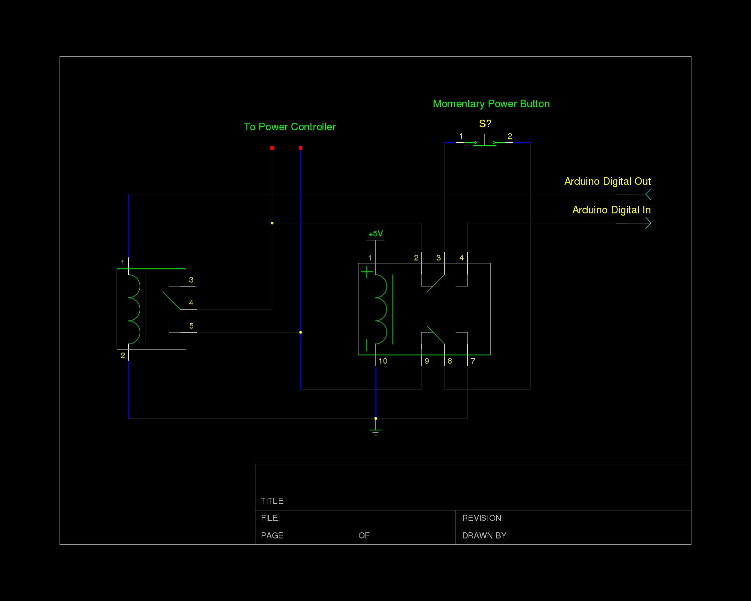
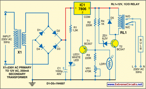
The power controller module in the system receives input directly from a momentary switch and utilizes this input to toggle a relay, which supplies mains power to the system's transformers. The controller circuit operates at 12V, a choice made...