
DIY Stepper Controller Circuit

The electronic schematic described involves several critical components that work in concert to provide effective control of a stepper motor. The power input section is crucial as it supplies the necessary voltage levels for the entire circuit. The raw +12V input is essential for driving the stepper motor, while the LM317 voltage regulator ensures that the L297 receives a stable +5V supply. This is achieved through a voltage divider configuration using resistors of 240 ohms and 720 ohms, which sets the output voltage to the required level for proper operation.
The L297 is an integrated circuit that acts as a controller for the stepper motor. It requires four inputs: ground, step input (clock), direction, and enable. The step input determines the stepping frequency of the motor, while the direction input sets the rotation direction. The enable input allows the user to activate or deactivate the motor control. Based on these inputs, the L297 generates the necessary control signals to drive the L298 stepper motor driver.
The L298 is a dual H-bridge driver capable of controlling the direction and speed of the stepper motor by managing the current flow to its coils. It is vital to implement current sensing using 10-ohm resistors connected to its sense pins (pins 1 and 15). This setup limits the output current to 300mA, which is crucial for preventing overheating of the L298. If the sense pins are shorted to ground, the driver will be unable to regulate current properly, leading to excessive heat generation that can damage the component.
In summary, this schematic integrates a power regulation system, a stepper motor controller, and a driver circuit, ensuring efficient and safe operation of the stepper motor. Proper attention to component specifications and connections is essential for reliable performance and longevity of the circuit.The schematic for the board can be seen below. The three main elements of the board are (1) the power input and voltage regulation, (2) the L297 input and outputs and (3) the L298 stepper motor control circuit. While the motor is powered by a raw +12v input, there is a voltage regulator circuit for +5v going to the L297.
The LM317 uses a voltage divider 240 © and 720 © on its output and adjust pins to create this +5v output. The L297 has 4 inputs supplied by the user, a ground, step input (clock), direction and enable. From these inputs the L297 decides what outputs should be given to the L298 in order to control the stepper motor properly. The L298 will constantly be supplying current to the stepper motor unless you add additional sensing circuitry, so make sure you don`t forget the 10 © resistors off of pins 1 & 15, the sense pins.
This limits the current to 300mA and means out L298 won`t get hot enough to burn finger tips. If you want to see what I mean, connect pins 1 and 15 directly to ground and the L298 will burn up. 🔗 External reference
Related Circuits
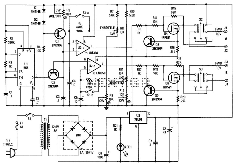
A 555 timer (U1) is configured as an astable multivibrator (oscillator) with a duty cycle of 400:1 and a frequency of 40 Hz. When power is applied to the circuit, capacitor C1 (connected to pin 6 of U1) is...
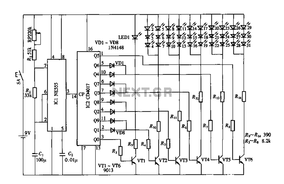
An electronic decorative peacock consists of 10 light-emitting diodes (LEDs), each of which contains multiple LEDs arranged in the tail of the peacock model. The light emission drive circuit operates the fan-shaped LEDs in a cyclic manner, emitting light...
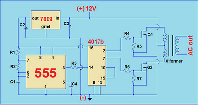
This project involves a simple 12V to 220V modified sine-wave inverter utilizing a 555 timer IC and a CD4017 decade counter. The inverter is capable of delivering 300W of continuous power and approximately 500W of maximum power output for...
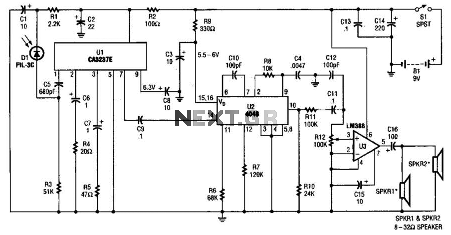
The infrared (IR) detector diode D1 captures the IR signal at approximately 40 kHz and transmits it to U1, a high-gain preamplifier, which then sends the signal to U2, a 4046 phase-locked loop (PLL) configured as a frequency modulation...
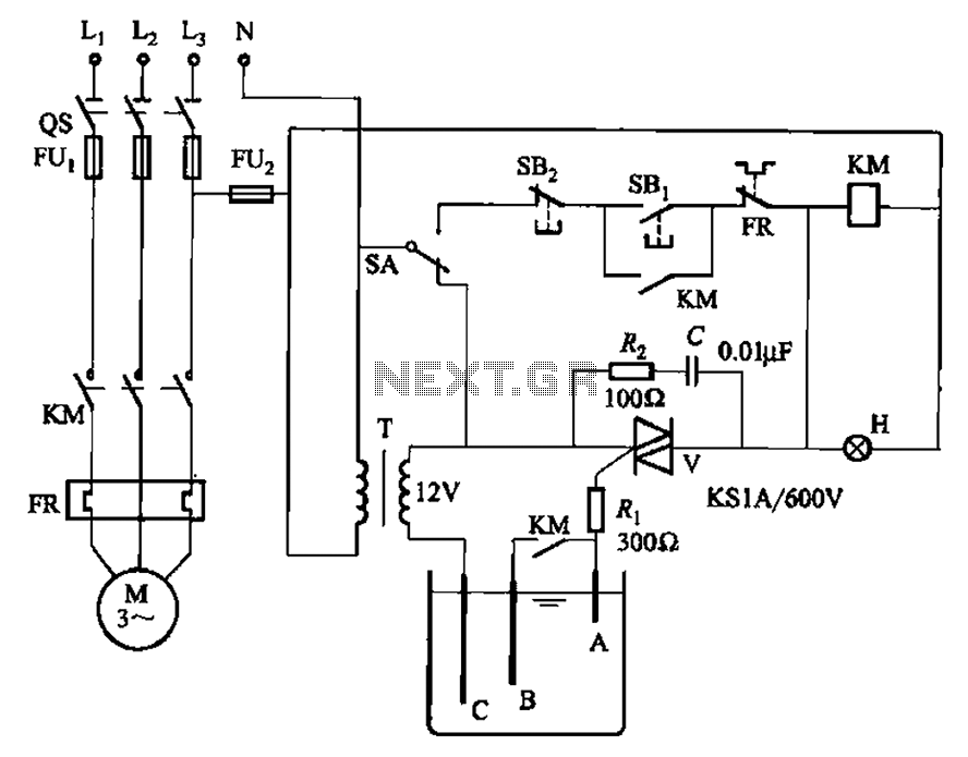
Bidirectional thyristor control manages the trigger voltage output from the step-down transformer at 12V when the water activates the electrodes. It is part of a drawable circuit that regulates the level. The circuit includes a current-limiting resistor (Ri) to...
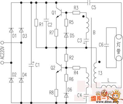
The saving lamp circuit features two main types: glass cover and exposed. The glass cover variants include three series: spherical, cylindrical, and processing types. The first two series consist of four variations: transparent, carved, engraved, and white. These lamps...